|
|
|
Categories
|
|
Information
|
|
Featured Product
|
|
|
 |
|
|
There are currently no product reviews.
 ;
I was very satisfied with the service manual I ordered and downloaded. I will definitely buy again from this seller.
;
Great product. Recieved it fast...exactly as advertised.
;
Manuals were delivered promptly and were correct as advertised. No issues with the download link which was provided promptly after everything was processed. Very pleasant experience
;
Paid for service manual & got the download fast - worth a visit if you need a service manual
;
It's the manual, I am searching for. Now I am able to repair my Braun A501.
DVD-302, DVD-U02
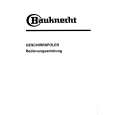
8. PANEL FACILITIES AND SPECIFICATIONS
PANEL FACILITIES
÷ FRONT VIEW for DVD-U02
7
DVD-ROM DRIVE
REAR VIEW
1
4
PHONES DVD BUSY
1
8
1
49 50
1 2
DC INPUT +5 G G +12
6
5
4
3
2
8
9
0
-
1 Disc loading slot
Insert the DVD-ROM or CD-ROM with the label facing up.
8 Audio output
This is a connector for output of analog audio. As a Molex 70553 type connecter is used, select a matching connection cable.
Precautions on Playing 8 cm/3-inch Discs ¶ When playing 8 cm/3-inch discs, always use the adapter for 8 cm/3-inch discs. Before loading the disc into the DVD-ROM drive unit, be sure to check that it is secured properly by the catches of the adapter. If discs have been inserted without the adapter by mistake, remove the disc immediately by pressing the eject button. If the disc does not come out with one press, press another time. ' ¶ Use 8 cm/3-inch disc adapters labeled with the mark (recommended standard product). Do not use adapters which cause the disc to idle, nor adapters which are bent or curved.
9 Function switch
Use the accessory short-circuit sockets to set the SCSI ID number and the drive function. ÷ ON : short circuited ÷ OFF : open #1 ~ 3 : SCSI ID SCSI-ID Setting switch 0 1 2* 3 4 5 6 7 0 (LSB) (#1) OFF ON OFF ON OFF ON OFF ON 1 (#2) OFF OFF ON ON OFF OFF ON ON 2 (MSB) (#3) OFF OFF OFF OFF ON ON ON ON
2 Eject (0) button
This button is used to eject the disc.
* The factory setting is for ID No. 2. #4 : #5*1 : #6 : Reserved SCSI Terminator ON = SCSI termination disable OFF = SCSI termination enable Default sector size ON = 512 byte OFF = 2048 byte Disable the eject switch ON = Disables the eject switch OFF = Enables the eject switch RPC (Region Play Control) Set ON = Stay in RPC Phase I mode OFF = Start RPC Phase II mode (Never return to Phase I mode after Phase II mode is used)
3 BUSY indicator
Flashes during data access.
4 DVD indicator
Lights when a DVD is loaded.
5 Volume Control (headphone level)
This is used to adjust the volume level of the headphone jack. #7 : #8*1*2 : This is a stereo minijack for headphones.
6 Headphone jack (PHONES) 7 Forced ejection hole
When the eject button has lost its function, insert an accessory pin for emergency ejection into this hole and push to eject the disc. WARNING: ÷ Before executing this operation, be sure to switch off the powe supply of the computer and confirm that the disc loading is stopped. It takes approx. 30 seconds to stop loading a disc after switching off the power supply. ÷ Always use the pin provided (Do not use other objects).
*1 *2
Pin 5 (TERMINATION) and Pin 8 (RPC SET) are ON at the time of shipping from the plant. For a DVD Video playback system (computer) for Phase I, please use with Phase I. When the DVD Video playback system (computer) and the drive have different region codes, DVD Video playback is not possible. Set the jumper switch to OFF only when use of a drive corresponding to Phase II has been specified clearly for the DVD Video playback system (computer). The drive will be initialized automatically and will operate in Phase II mode.
0 SCSI interface
This is a 50-pin I/O connector according to the SCSI-2 specifications. Use a flat ribbon SCSI connector to connect to the SCSI host adapter.
- DC Input
This is the power supply input for DC +5 V and +12 V.
32
|
|
|
> |
|