|
|
|
Categories
|
|
Information
|
|
Featured Product
|
|
|
 |
|
|
There are currently no product reviews.
 ;
A manual hard to find. It was very helpful to restore my device.
;
I am very grateful for this manual. Without it could not repair my receiver.
;
excellent work as always you do cheap, fast net and clean. you do an incredible service......thanks!
;
Great Job even clear than the one before!!!! god organization- I'm always very satisfied
;
I'm very happy that you all are performing an incredible good job. Furthermore what you did is very useful for all people as me that have electronics as an hobby.Thank you!!!!!
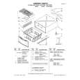
[25] (C-3) [23] (S-15) [26] (P-4) [27] (C-6) [29] (C-4) [28] [30] [24] [31] (L-4) (C-2) [22] (C-5)
(P-4) [28]
Pin on bottom of [23]
When installing [23], install the spring (P-4) to [28] as shown in the left figure, and then install [23] while pressing the spring (P-4) to the direction of the arrow in the left figure and confirming that the position of the spring (P-4) is placed as shown in the left figure. [23]
[32] Position of Mode Lever when installed Pin of [34] Pin of [37] Pin of [38]
Bottom View [25] [28]
Top View Align [25] and [28] as shown. First groove on [28] First tooth on [48] [28] When reassembling [28], meet the first groove on [28] to the first tooth on [48] as shown.
Pin on [22]
[28] Top View Position of pin on [22]
Fig. DM14 Fig. DM13
2-4-7
HC460DA
|
|
|
> |
|