|
|
|
Categories
|
|
Information
|
|
Featured Product
|
|
|
 |
|
|
There are currently no product reviews.
 ;
I am a vintage hifi collector. No way to fix that device without the appropriate service manual...thanks to your site I got it and every thing is easier now. I got the manual right after ordering: fast cheap accurate ... thank you
;
Wonderful job clear. Qick fantastic. These people are really good. If even a problem arise they are wonderful assisting you. These scheme is so net despite this is a very old TV. Thank you for everything!!!!!!!!
;
Detailed schematic diagram, manual for professionals
;
Good service manual,exploded view,adjusment and test point locations,head alignment,mechanical checks and adjusments,all perfect.
;
Block diagram,play rec block diagram,adjusments, it's a very good well done repair manual.
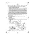
Mechanical Instructions 4.7 Sledge Motor Assembly
Caution: Never try to align or repair the DVD-Module itself! Only the factory can do this properly. Service engineers are only allowed to exchange the sledge motor assy. � Place the DVD-Module, with the laser facing downwards on a soft surface. � Remove the three screws that hold the sledge-motor assy and lift the assy upwards. You can replace it now.
VAD 8031
4.
EN 7
Figure 4-6 Remove Sledge Motor Assy
4.8
Re-assembly
To re-assemble the module, do all processes in reverse order. Take care of the following: � Sledge-motor assy: Mesh the teeth of the sledge motor and sledge rack properly, during mounting of the sledge motor assy. � Heat Paths: Put the 5 heat paths (gray rubber pieces) back to their position on the ICs, see figure 4-7. � Complete module: Place all wires/cables in their original positions � Emergency opening slot: Be sure that the slot for the emergency tray opener is covered by adhesive tape! � Jumper selection: Jumper has to be in position "Master"!
Figure 4-7 Heat Paths
|
|
|
> |
|