|
|
|
Categories
|
|
Information
|
|
Featured Product
|
|
|
 |
|
|
There are currently no product reviews.
 ;
Great Job even clear than the one before!!!! god organization- I'm always very satisfied
;
I'm very happy that you all are performing an incredible good job. Furthermore what you did is very useful for all people as me that have electronics as an hobby.Thank you!!!!!
;
Manual found fast and good quality, very helpfull service
;
8-17-12 Been using the sight for about 6 months. Fast Downloads and top quality
Manuels !
 ;
Everything was great, the manual, the response time, the simplicity of the order, and the
Price. The only thing that I could possible say on a negative note would be that the manual I ordered was more for a service tech. There were a lot of schematic diagrams that didn't help me solve the problem. However I would order again and recommend the web sight to others.
DVD-S29GCS / DVD-S29GCU / DVD-S29GN / DVD-S29PLA / DVD-S29PL / DVD-S29EE / DVD-S29GCA / DVD-S29GC / DVD-S29GD / DVD-S29PX
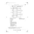
7.3.
Tray
5. Remove the drive arm concave phase from the tray slider and tray.
1. Slide the guide tray unit while pressing the stopper in the arrow direction, and remove the guide tray unit.
2. Raise the loading unit. 3. Slide the lever in the arrow direction till it stops and pull the tray out.
<Assembling the tray unit> 1. Insert a part of the tray into the unit sliding over the groove on the mechanical chassis unit. 2. Insert the tray to the point before the tab of the mechanical chassis unit.
4. Spread the tabs at the both sides and pull the tray out. (The tray slides a little forward and stops.)
3. Hook the drive arm concave phase over the tray and the tray slider. 4. Press in the tray. 5. Make sure that the tray and the drive arm move smoothly.
13
|
|
|
> |
|