|
|
|
Categories
|
|
Information
|
|
Featured Product
|
|
|
 |
|
|
There are currently no product reviews.
 ;
as always, rapid and efficient, very good and clear prints
details clearly visible keep going this way!!!!!!
;
I expect a wonderful result as alaways!!!!!!
Usually is much faster....
;
Wow very wonderful and clear!!!! I will always trust them
;
Providing the manual works fine, quickly and without any problems for an acceptable price. After printing the service manual it took me only a short time to repair my carradio from Clarion. Thank You! Greetings from Heiko
;
I was searching a way to modify the original phono-in entry (for connection of vynil disc player, with RIAA equalization) to a line-in entry (for connection of modern analog entries, eg. ipod, mp3player).
This service manual gave me the correct hints.
It contains very useful infos for repairing and modifing the hi-fi, such as disassembling instructions, block diagrams, schematic diagrams, PCB prints, replacement parts list.
Very good!
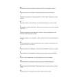
DV-F727, DV-F07
2 Disc-select Rotation Adjustment
DC power supply
Connection Diagram for Adjustment
V
A
�8V GND +8V
VOLB ASSY
VR601 KN601 Player
JIG (Peak hold circuit)
Digital multimeter
SW INPUT OUTPUT
GND (Under Base)
Adjustment Procedure
1. 2. 3. 4. 5. 6. 7. 8. 9. 10. 11. 12. 13. 14. Connect all equipment as shown in the diagram. Turn on the power (Normal mode) and put the test disc in the No. 1 disc slot. Enter the Test mode by pressing the "ESC" � "TEST" button of the test mode remote control unit. Press the "DIG/ANA" button of the test mode remote control unit. (Disc 1 is clamped.) Adjust VR601 on the VOLB Assy so that the voltage becomes 830 ± 5mV. Switch the connection of Digital multimeter from INPUT to OUTPUT of the Jig. Press the "DIG/ANA" button of the test mode remote control unit. (Starts the disc detection and peak hold .) Confirm the voltage during the disc detection. If voltage is between 920 to 1170mV, go to step 13. If not, go to step 9. Switch the connection of Digital multimeter form OUTPUT to INPUT of the Jig. Press the "DIG/ANA" button of the test mode remote control unit. (Disc 1 is clamped.) Adjust VR601 to become the value for addition (or subtraction) that to have an adjustment voltage. (Refer to the following table.) Perform steps 6 to 8 again and confirm the voltage during the disc detection. If voltage is between 920 to 1170mV, go to step 13. If not, repeat steps 9 to 12. Confirm that Disc No. display doesn't become "1" others when you turn the Jog dial. Release the Test mode by pressing the "ESC" button or turn off the power. Adjustment voltage value Peak hold voltage (mV) to 859 859 to 879 879 to 920 920 to 1170 1170 to 1309 1309 to 1520 1520 to 1840 1840 to 2220 2220 to Adjustment voltage (mV) +20 +10 +5 OK -5 -10 -20 -30 -40
64
|
|
|
> |
|