|
There are currently no product reviews.
 ;
Hard to find manual was ready the next day. Scans were very legible (including schematics). All the essential parts of the service manual were present (adjustment procedure, schematics, and parts list). It would have been nice if the rest of the manual was included (disassembly procedure, theory of operation, etc.).
 ;
The Service Manual for the Kenwood KR-V55R provided by owner-manuals.com was as described/advertised. The contents provided the necessary information to effect a diagnosis of the unit. The schematics above all else was instrumental in tracing the the signal flow from component to component.
;
This manual was the factory original. Excellent value and contained all the details I needed. Easy dowwnload provided the information when I needed it.
;
Impeccable, document très complet. Perfect, i get all i need. All schematic are correct. Thanks
;
The manual is of better quality compared to other. I found it less expensive and therefore it it is the best buy cost vs quality.
DV-5050M/5900M/DVF-J6050/J6050-G
ADJUSTMENT
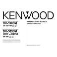
DVF-J6050 E version No. 1 ITEM INPUT SETTING 100% COLOR BAR DISC OUTPUT SETTING Connect the oscilloscope to composite(X13,J4) with 75-ohms resistor ALIGNMENT POINT VR301(X35) ALIGNMENT FOR Y-signal = 1000mV±30mV Chrom-signal = 300mV±15mV FIG. FIG.1.
Y LEVEL
2
CHROM LEVEL
� 100% COLOR Connect the oscilloscope to BAR DISC composite(X13,J4) with 75- VR304(X35) � PAL DISC (PAL MODE) ohms resistor Connect the oscilloscope to Y output(X13,J6) with 75-ohms resistor VR600(X25)
FIG.2.
3
YCb Cr LEVEL 100% COLOR (DVF-J6050 only) BAR DISC
Y-signal = 1000mV±30mV
FIG.1.
[mV]
700(100IRE)
700
white yellow
623 490
cyan green 413 magenta 287 red
210
blue
77
1000mV±30mV
black
0
0
4.7µs
-300
Y
Fig. 1
IRE Peak white
Y Level 1000mV ±30mV
C Level 300mV ±15mV
0 Blank
Sync. chip
Fig. 2
27
|