|
|
|
Categories
|
|
Information
|
|
Featured Product
|
|
|
 |
|
|
There are currently no product reviews.
 ;
The scan is clear and well readable with very few weaker spots, usually on black background with white letters, but with enough zoom those spots can be read.
Printout is clear, the manual is complete and has all pages scanned.
I would give 5 stars, except that it is not in color, and the schematic and PCB pages are scanned on multiple pages. The document is locked (except printing) so the pages can not be extracted to compose them together for printing on the large plotter
It is worth the price tag.
 ;
let's say first that i do not need to have a credit for my opinion, i am a retired sparkie and i voluteerd to fix an electronic device for a local "Youthgroup",as no diagram was present i checked the "net" and gambled on this site and paying some fee via PayPall, i was gladly surprised that the manual arrived as was stated, GOOD SHOW, and best wishes, John
;
I had been looking for a Manual for my CS2150 for quite a while -- in fact I had just about given up. I saw this site and decided to download the Manual. When I Received it by Email I was really pleased with what I got, with the result that My Kenwood 'Scope is now 100% repaired and working well. As an AV Serviceman, you need a good 'scope, and thanks to this site, and the Service Manual, I have been able to repair it. The Manual was a copy of the Factory Original and the copy was very clear, especially in the area of the Circuit Schematics, where You really need to be sure of what You are looking at.
;
I recently purchased a manual for a Samsung DLP tv to help with a trouble shooting problem I was having. Every tv repair shop wanted close to $400.00 for the fix, but after I found Owner-Manuals.com I hit pay dirt. The manual they had for me to purchase and download was a complete service manual for the exact tv I needed. It was complete with wiring diagrams, schematics, and even part numbers. If your the fix it yourself type I highly recommend trying to find any manual here before paying someone else to fix whatever problem your having.
;
Once again, excellent price and manual delivered in a timely manner and as advertised!
DV-5700/DVF-R9050/R9050-S
ADJUSTMENT
No. ITEM INPUT SETTING OUTPUT SETTING ALIGNMENT POINT VR601 ALIGNMENT FOR Y-signal = 1000mV 30mV FIG. Connect the oscilloscope to 100% COLOR BAR DISC Y output with 75-ohms resistor. Output Mode: Interlace 100% COLOR BAR DISC Connect the oscilloscope to COMPOSIT output with 75ohms resistor.
1
Y,Cb,Cr LEVEL
FIG.1
2
Y LEVEL
VR600
COMPOSIT-signal = 1000mV FIG.2 30mV
You need the step 1and 2 before next step 3
3
CHROM LEVEL
Connect the oscilloscope to 100% COLOR BAR DISC COMPOSIT output with 75ohms resistor Connect the oscilloscope to 100% COLOR BAR DISC Y output with 75-ohms resistor. Output Mode: Progressive
VR602
Chrom-signal = 286mV 14mV Y-signal= 1000mV±30mV
FIG.2
4
Progressive Y, Cb, Cr LEVEL
VR800
FIG.1
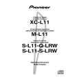
IRE' Peak white [mV]
714 (100IRE)
714
white yellow
641
100
cyan 516 green 443 magenta 324 red
252
blue
127
black
54
1000mV 30mV 1000mV 30mV
286mV 0 ±14mV
Blank
0
4.7 s
-2.86
Y
-40
Sync. chip
Fig. 1
Fig. 2
26
|
|
|
> |
|