|
There are currently no product reviews.
 ;
Fully functional usable service manual. Considering the age of the manual and device quality was better than expected
 ;
Thank you very much, I've been very happy to find this manual on "Owner Manual". It's a perfect copy and it has been really useful for my work!
;
It took about 24-hours after my payment before I was able to get to the download. Apparently, payment processing is not 100% automated. That is no big deal, just be aware of that going in.
After I got to it, it was in good shape, easy to read, etc. Not some cheap FAX copy looking thing.
Also, this site was the cheapest I found. Another Plus!
;
Good price, very legible manual, exactly what I needed -- but had to wait a day to actually get the download of the manual. Would have preferred to download it immediately after payment rather than waiting for someone to "process" my order. I was surprised that I had to wait that long.
;
As the only source for this manual it rather rank quite high since it is well scanned and perfectly readable.
1
2
3
4
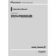
7. DISASSEMBLY
- Removing the Keyboard Unit (Fig.1,2)
A
Remove the Knob Unit.(Fig.1)
Knob Unit
1
Remove the six screws.(Fig.2) Cover Detach Grille Assy Fig.1
Remove the Cover and then remove the Keyboard Unit.
1 1 1 1
Fig.2
B
1
- Removing the Holder, Panel and Case (Fig.3) Take off the pick of left and right and then a Holder slide to the arrow course. Remove the Panel. Remove the Case.
1
Fig.3 Panel Holder Pick Case
C
- Removing the Panel Unit (Fig.4,5,6,7)
1
Remove the two screws.(Fig.4,5)
Panel Assy
Push the place of the arrows and then remove the Panel Assy.(Fig.4,5)
1
Fig.4 Holder
1
Fig.5
D
2
Remove the two screws.(Fig.6)
Remove the Holder and then remove the Panel Unit.(Fig.7)
2
2
Fig.6 - Removing the DVD Mechanism Module (Fig.8)
Panel Unit
Fig.7
E
1
Remove the four screws.
1 1
Disconnect the cable and then remove the DVD Mechanism Module.
1
Fig.8
1
F
DVD Mechanism Module
66
DVH-P6050UB/XN/CN5
1 2 3 4
|