|
|
|
Categories
|
|
Information
|
|
Featured Product
|
|
|
 |
|
|
There are currently no product reviews.
 ;
THANK YOU FOR A GOOD TRANSACTION, NICE COPY, CLEAR
;
Very Good! All the diagram are easy to read, and its complete.
;
This was an excellent source of detailed assembly information on a device which is at least 12 years old. A very lucky find, coupled with great service.
;
Excellent Service Manual and best price on the Internet. This Service Manual covers everything you could ever need including full circuit schematics, component layout diagrams, stripdown procedure and full parts list/breakdown. I needed this to carry out a modification to one of these headunits and this manual covered everything I needed. Fast delivery, processed within a few hours.
 ;
Thought I would never find a copy of the Technics SX-EN2 Service Manual until I found Owner-Manuals.com. Price was very fair and I received the download promptly. While a photocopy, it is quite readable and includes all the pertinent information and diagrams. Thank you Owner-Manuals!
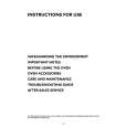
CIRCUIT OPERATION
1-3) PB MODE
When playing the tape, the signal which is picked up from the tape is amplified 50 dB. Then luminance signal goes to pin 11 and color signal goes to pin 7 through AGC. Luminance signal of pin 11 is input to pin 39 of IC301 through PB EQ circuit in order to match playback characteristic. Color signal which is output from pin 7 of IC401 is input to pin 15 of IC301. PB FM signal is demodulated by IC internal demodulator then it is input to pin 3 after MAIN DE-Emphasis process. If this output signal has burst, color component will be separated by X303. If it has burst, it is input to pin 4 of IC301 through Yemphasis circuit. The signal which is input to pin 4 is output from pin 12 through 3.5M LPF, then it is input to pin 10 through 1H CCD. Color signal which is input to pin 15 passes ACC in order to stabilize level, then 3.58H components will be extracted by 3.58M BPF through Main Converter. This 3.58M color signal is input to pin 25 of IC301 in order to eliminate crosstalk, then it will be mixed with luminance signal after passing CNR circuit. Finally Y/C composite video signal is output from pin 34.
X302 IH DLY
V-OUT
V.IN
IC301 VIDEO IC Y-EMPH
X303 Y/C COMB
PB EQ
IC401 HEAD AMP
IC302 IH CCD
17
|
|
|
> |
|