|
|
|
Categories
|
|
Information
|
|
Featured Product
|
|
|
 |
|
|
There are currently no product reviews.
 ;
The manual was exact the thing that was promised. My old car stereo is working again thanks to the information supplied.
;
I PURHASED THIS PRODUCT BECAUSE I WAS HAVING PROBLEMS WITH MY CDR20 HARMAN KARDON RECORDER. WHICH I PURCHASED NEW 12 YEARS AGO. AFTER REVIEWING THE MANUAL, I WAS ABLE TO ADJUST THE TENSIONER IN THE SYSTEM. WORKS LIKE A CHAMP!.
SAVED ME AT LEAST 100.00 WHICH WAS WHAT A SERVICE REPAIR STATION WANTED. GREAT MANUAL EASY TO READ. SPECIALLY AFTER I PRINTED THE PAGES WHICH DEALT WITH MY RECORDER. THANKS A LOT!!!!!!!!
 ;
You can fully trust on this one!
All the schematics are very crear an in one piece per page
;
I have never bought a service manual which is as competely readable as this althogh it was a scanned pdf. Thank you for this succesful manual also cheaper than other sites.
;
Thanks for a very good and readable servicemanual. Just what I needed as a "dinosaur technician". I really recommmend this site and will come back.
Åsbjörn
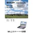
DV-L70S DV-L70BL DV-L70W
5. DISASSEMBLY METHOD
5-1. DISASSEMBLY METHOD
1. Remove the nine screws 1. 2. Loosen the two screws 2. 3. After opening the LCD unit, remove the hinge claw of cabinet A to detach it from cabinet B. Note: The power SW button is also removed. Be careful not to forget it when assembling the unit. 4. Remove the FFC A from the main PWB.
1
2
A
Power SW Button
5. Remove the screws 3. Note: Check the screws before assembling because they are different depending on the right and left hinges. 6. Remove the connector 4 from the main PWB. 7. Remove the pickup FPC/sled lead connector 5. 8. Remove the screws 6 fixing the DC jack PWB.
5
5 6
4 3
9. Remove the four LCD rubber caps 7. 10. Remove the four screws 8. Note: Be careful not to forget to put space washers when assembling because they are tightened with the above screws. 11. Remove the cabinet D. At this time, remove engagement claws (two on the upper LCD panel, two on the right and left sides, two on the lower LCD panel). Note: Do not break the claws on the right and left sides by opening cabinet C a little. 12. Remove the right and left speaker connectors 9.
8
7
Space Washer
7 8
Space Washer 9
10
13. Remove the screw 0. 14. Remove the FPC q from the connector. 15. Remove the screw w. 16. Remove the FPC e from the connector. 17. Remove the screw r. 18. Remove the connector t.
11 14 11
13
12
15
19. Remove the four screws y. 20. Remove the three claws on the control panel (front: 2 pcs., rear: 1 pc.). 21. Open the disc cover u 180� to remove it from cabinet A.
17
16
7
|
|
|
> |
|