|
|
|
Categories
|
|
Information
|
|
Featured Product
|
|
|
 |
|
|
There are currently no product reviews.
 ;
Good product. All the information is invcluded, but due to the complexity of the amplifier, it still is difficult to get it to operation again.
 ;
Very professional seller; very fast, accurate and rielable service.
;
great works fine, got the manual on mail within a day
;
First class Service,
best quality, come again
Thank You.
vac
;
I didn't realise a manual for an early plasma TV such as the one we were gifted could be so easily obtained. No manual was supplied with it, and as senior citizens we were a little puzzled over some aspects of its use. I do not want a listing for your store credit as we are not fairly big computer users. The manual was well organised, as it should be, with its backing of the Pioneer name. The download was prompt and everything worked quite smoothly. Thank you. Gordon.
How to Remove / Install Flat Pack-IC
1. Removal
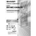
With Hot-Air Flat Pack-IC Desoldering Machine: (1) Prepare the hot-air flat pack-IC desoldering machine, then apply hot air to the Flat Pack-IC (about 5 to 6 seconds). (Fig. S-1-1)
With Soldering Iron:
(1) Using desoldering braid, remove the solder from all pins of the flat pack-IC. When you use solder flux which is applied to all pins of the flat pack-IC, you can remove it easily. (Fig. S-1-3)
Flat Pack-IC Desoldering Braid
Soldering Iron Fig. S-1-3
Fig. S-1-1
(2) Remove the flat pack-IC with tweezers while applying the hot air. (3) Bottom of the flat pack-IC is fixed with glue to the CBA; when removing entire flat pack-IC, first apply soldering iron to center of the flat pack-IC and heat up. Then remove (glue will be melted). (Fig. S-1-6) (4) Release the flat pack-IC from the CBA using tweezers. (Fig. S-1-6) Caution: 1. Do not supply hot air to the chip parts around the flat pack-IC for over 6 seconds because damage to the chip parts may occur. Put masking tape around the flat pack-IC to protect other parts from damage. (Fig. S-1-2) 2. The flat pack-IC on the CBA is affixed with glue, so be careful not to break or damage the foil of each pin or the solder lands under the IC when removing it.
(2) Lift each lead of the flat pack-IC upward one by one, using a sharp pin or wire to which solder will not adhere (iron wire). When heating the pins, use a fine tip soldering iron or a hot air desoldering machine. (Fig. S-1-4)
Sharp Pin Fine Tip Soldering Iron
Fig. S-1-4
(3) Bottom of the flat pack-IC is fixed with glue to the CBA; when removing entire flat pack-IC, first apply soldering iron to center of the flat pack-IC and heat up. Then remove (glue will be melted). (Fig. S-1-6) (4) Release the flat pack-IC from the CBA using tweezers. (Fig. S-1-6)
Hot-air Flat Pack-IC Desoldering Machine CBA
With Iron Wire:
(1) Using desoldering braid, remove the solder from all pins of the flat pack-IC. When you use solder flux which is applied to all pins of the flat pack-IC, you can remove it easily. (Fig. S-1-3)
Masking Tape Tweezers
Flat Pack-IC
(2) Affix the wire to a workbench or solid mounting point, as shown in Fig. S-1-5. (3) While heating the pins using a fine tip soldering iron or hot air blower, pull up the wire as the solder melts so as to lift the IC leads from the CBA contact pads as shown in Fig. S-1-5.
Fig. S-1-2
1-4-2
DVD_NOTE2
|
|
|
> |
|