|
|
|
Categories
|
|
Information
|
|
Featured Product
|
|
|
 |
|
|
There are currently no product reviews.
 ;
Excellent!! Got what I need and very fast!! Thank You
;
Manual acquired with good resolution, complete in all its pages, very good policy of the folder where are saved all products purchased.
 ;
Service manual very complete and clear. It was very helpfull for my work.
;
This is the 2nd time I download manuals from this website and I can say it's what I was expecting. It contains schematic, layout (decent quality), short description, parts and dissasembly instructions. I recomend it for anyone who wants to repair/modify this device.
;
Very useful Service Manual! With it I was able to identify the damaged pots in my old amplifier, purchase the adequate replacements and make myself the repair.
I have again my old amplifier, still a very good one that I will keep for as many years as I can!
Thanks to Owner Manuals!
DV-NC55S/H DV-NC60H
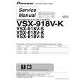
8-27.INSTALLING THE MASTER CAM (AT REAR SIDE OF MECHANISM CHASSIS)
1. Make sure beforehand that the shifter is at the point as shown below. 2. Place the master cam in the position as shown below.
8-28. REPLACEMENT OF LOADING MOTOR
� Removal
E ring (XRESJ30-06000) Master cam Apply grease Apply grease
Fully turn clockwise
Fully turn counterclockwise Face the wide tooth side ward No grease
Figure 8-45-1.
Note: See the figure below for the phase matching between the master cam and the casecon drive gear. 3. Finally fix with the E ring.
Master cam
Figure 8-46.
Casecon drive gear
Half-round notch Round mark
� Replacement Remove the loading motor, and install the replacement loading motor as shown below.
10.2 +0.2 mm �0.2
When installing the master cam, align the casecon drive gear round mark with the half-round notch of master cam.
Figure 8-45-2.
Figure 8-47. The loading motor pressing-in must be less than 147 N (15 kgf). Adjust the distance between motor and pulley to 10.2 +0.2 mm).
�0.2
36
|
|
|
> |
|