|
|
|
Categories
|
|
Information
|
|
Featured Product
|
|
|
 |
|
|
There are currently no product reviews.
 ;
Speedy transaction with a quick download. Awesome hassle-free service.
;
very poolite and healpful secure transaction thanks allot
;
- Very good scan quality, PERFECT!
- Sehr gute scan Qualitaet, empfehlenswert!
Wolfgang Sundhaus
 ;
Good site, works ok and you get what you order, no problems experienced, got my manual within a day. A++++
;
Original well scanned manual. Got the job done. Microwave problem found & corrected. For $5 and a new magnitron from ebay, it was a cheap and good the first shot fix. Electrical schematics allowed me to mage sure every thing else was ok before cutting and order for parts. Hard to live without.
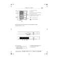
2. PLAYBACK Y-SINGAL OUTPUT LEVEL Adj. Location RV396 Checking Point TP396 Measuring Equipment Oscilloscope Mode PB Test Tape DP-1
1) Playback the test tape (Color Bar Signal). 2) Connect the oscilloscope to TP396 and trigger the scope will a composite SYNC signal at TP313. 1) Adjust the scope so that it can display a waveform of approx. 2H. 3) Adjust RV396 to optain 2.0VP¡ 0.2 Vp-p between the SYNC TIP and 100% white level.
2.0¡ 0.2Vp-p
Horizontal 10Â¥s/div Vertical 0.5V/div.
3. SYNC TIP FREQUENCY Adj. Location RV391 Checking Point TP391 Measuring Equipment Oscilloscope Mode REC. Test Tape �¡
1) Set the unit to stop mode without video signal. (Jack of video line input is shorted with ground). 2) Conncet the frequency counter to TP391. 3) Adjust RV391 until the SYNC TIP frequency becomes 3.80 MHz¡ 0.1 MHz.
7
|
|
|
> |
|