|
|
|
Categories
|
|
Information
|
|
Featured Product
|
|
|
 |
|
|
There are currently no product reviews.
 ;
This service manual helped me to repair my PIONEER. Iam very satisfied, that I found it here.
Even the price of manual was not so high that person would not be able to spend a few money.
But that is very worth spent money. Thanks
 ;
Excellent quality service manual. Quick processing, fair prices. Love to do business again. Thank you!!!
;
Excellent service manual, the only known point of note is the alignment of improvability scanned pages within the pdf page. The resolution is good.
;
I was very glad recieving the service manal from You. Additionaly very fast. Extremaly nice servicing. Thanks very mach! Now my GX-220 working better, than it was made. Alexander from Moscow, Russia/
;
Sweet! I won the item on eBay and couldn't adjust the geometry or even keep a steady picure. This guide has the full schematics (not available anywhere else as far as I could tell), and was a bargain for the wealth of knowledge it contains. I hooked it up to my testing equipment, tweaked a few potentiometers and got it playing videogames in no time. Thanks!
5
6
7
8
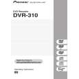
8.3 REAR PART
A
B
1
VHF/UHF IN/OUT
Front panel connections
Connect your TV antenna to the VHF/UHF IN jack. The signal is passed through to the VHF/UHF OUT jack for connection to your TV.
2
Audio/video inputs 1 and 3
Two sets of audio/video inputs (stereo analog audio; composite and S-video video) that you can use to connect to satellite receivers, TVs, VCR or other source component for recording.
On the left side of the front panel a flip-down cover hides a third audio/video input, consisting of an S-video and standard (composite) video jack, and stereo analog audio jacks. On the right side is the DV input/output i.LINK connector. This is for connection to a DV camcorder.
C
3
Audio/video outputs 1 and 2
Two sets of audio/video outputs (stereo analog audio; composite and S-video video) that you can use to connect TVs or monitors.
4
COMPONENT VIDEO OUT
A high-quality video output for connecting to a TV or monitor with a component video input.
5
DIGITAL OUT OPTICAL
D
A digital audio output for connecting to an AV receiver, Dolby Digital/DTS decoder or other equipment with optical digital input.
6
CONTROL IN
Use to control this recorder from the remote sensor of another Pioneer component with a CONTROL OUT terminal and bearing the Pioneer � mark. Connect the CONTROL OUT of the other component to the CONTROL IN of this recorder using a mini-plug cord.
E
7
AC IN
Connect to a power outlet using the supplied power cable after making all other connections.
F
DVR-310-S
5 6 7 8
121
|
|
|
> |
|