|
|
|
Categories
|
|
Information
|
|
Featured Product
|
|
|
 |
|
|
There are currently no product reviews.
 ;
Superb manual. Exactly what I ordered and made available in a very timely manner.
 ;
very fast detailed and accurate hope to do business again
;
This was precisely what I was looking for. Complete and good quality!
;
This is the ONLY copy of this manual I could find for a realistic price. Even Panasonic could not provide me with one.
The PDF is a very good copy and it helped me diagnose and find the fault with the unit I have.
;
Very complete and well reading drawings. Documentation is essential for successful repairs.Good documentation, with all that is necessary. This manual was what I was waiting with all the information necessary for the repairing I need it for. You must buy it if you want to do repairs or simply understand how it works.
5
6
7
8
8.3 REAR PART
A
B
1
VHF/UHF IN/OUT
Front panel connections
Connect your TV antenna to the VHF/UHF IN jack. The signal is passed through to the VHF/UHF OUT jack for connection to your TV.
2
Audio/video inputs 1 and 3
Two sets of audio/video inputs (stereo analog audio; composite and S-video video) that you can use to connect to satellite receivers, TVs, VCR or other source component for recording.
On the left side of the front panel a flip-down cover hides a third audio/video input, consisting of an S-video and standard (composite) video jack, and stereo analog audio jacks. On the right side is the DV input/output i.LINK connector. This is for connection to a DV camcorder.
C
3
Audio/video outputs 1 and 2
Two sets of audio/video outputs (stereo analog audio; composite and S-video video) that you can use to connect TVs or monitors.
4
COMPONENT VIDEO OUT
A high-quality video output for connecting to a TV or monitor with a component video input.
5
DIGITAL OUT OPTICAL
D
A digital audio output for connecting to an AV receiver, Dolby Digital/DTS decoder or other equipment with optical digital input.
6
CONTROL IN
Use to control this recorder from the remote sensor of another Pioneer component with a CONTROL OUT terminal and bearing the Pioneer � mark. Connect the CONTROL OUT of the other component to the CONTROL IN of this recorder using a mini-plug cord.
E
7
AC IN
Connect to a power outlet using the supplied power cable after making all other connections.
F
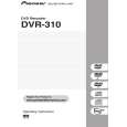
DVR-310-S
5 6 7 8
121
|
|
|
> |
|