Shopping cart is empty
 
English Polski Spanish 
Search For a Manual
 

(e.g. AA-V20EG JVC, ZX-7 Sony )
PayPal 1000+ rating Secure, Encrypted Checkout.
 
Categories
Information
Featured Product
Home >> TOSHIBA >> D-VR51KF Service Manual
 
 0 item(s) in your cart 

TOSHIBA D-VR51KF
Service Manual


Tweet about this product and get $1.00 of store credit for instant use!
  • Contains Circuit Diagrams
  • Download
  • PDF Format
  • Complete manual
  • Language: English
Price: $4.99

Description of TOSHIBA D-VR51KF Service Manual

Complete service manual in digital format (PDF File). Service manuals usually contains circuit diagrams, printed circuit boards, repair tips, wiring diagrams, block diagrams and parts list. Service Manual ( sometimes called Repair Manual ) is used mainly by technicians.

If You just want to know how to use Your tv, video, mp3 player etc. You should look for Owner's Manual. After placing order we'll send You download instructions on Your email address.

The manual is available in languages: English

Not yet ready
You must purchase it first

Customer Reviews
There are currently no product reviews.
Other Reviews
 VT-F430A HITACHI Service Manual by Thomas Hirz;
I needed the manual immediately and I got it immediately. I couldn't find this manual anywhere else on the net. The site was easy to traverse, and the price was very reasonable. I'll definitely be back for any future needs.
 AD-WX200 AIWA Service Manual by Angelo Gallina;
I received a good service manual, with good resolution. Improve the instructions for the purchase because they are not well understood. For the rest, so good. Thanks Angel.
 2077 GRUNDIG Service Manual by Herman Wiegman;
Very good documentation for the Grundig 2077 model (as well as similar 800/900/1000 series radios). The first two pages are a summary of reception specifications and output capability. The third page is the tuner dial indicator and dial cord routing diagram. the final ~5 pages are the schematics for the various models (including 2077). The scan quality of the schematics are good, adn can be easily read if zoomed in. The documents are in German, not English as stated. It would have been nice to have the tuning sequence and settings, and some trouble shooting materials... or component and wiring map.
 CA537P VOLUME 2 SONY Service Manual by Johannes Zündel;
Perfect like it was descriped, Perfect like it was descriped
 SR-838 SANSUI Service Manual by John McKenna;
Very good detail, all pages clear, exactly what I needed

Text excerpt from page 112 (click to view)
1-D. Azimuth Alignment of Audio/Control/ Erase Head
Purpose: To correct the Azimuth alignment so that the Audio/ Control/Erase Head meets tape tracks properly. Symptom of Misalignment: If the position of the Audio/Control/Erase Head is not properly aligned, the Audio S/N Ratio or Frequency Response will be poor. 1. Connect the oscilloscope to the audio output jack on the rear side of the deck. 2. Playback the alignment tape (FL6NS8) and confirm that the audio signal output level is 8kHz. 3. Adjust Azimuth Adj. Screw so that the output level on the AC Voltmeter or the waveform on the oscilloscope is at maximum. (Fig. M6) Note: Upon completion of the adjustment of Azimuth Adj. Screw, check the X Value by pushing the [PROGRAM ] or [PROGRAM ] buttons on the unit alternately, to check the symmetry of the envelope. Check the number of pushes to ensure preset position. The number of pushes of the [PROGRAM ] button on the unit to achieve 1/2 level of envelope should match the number of pushes of the [PROGRAM ] button on the unit from center. If required, redo the �X Value Alignment.�

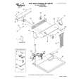
2. When the tape has been curled up or bent, turn the alignment screw to adjust the height of REV Post. (Refer to Fig. M11 and M13.)

REV Post [5]

Take-up Guide Post [4]

Fig. M11

Correct
REV Post Tape

Incorrect

Tape

Take-up Guide Post

1-E. Checking and Alignment of Tape Path during reversing
Purpose: To make sure that the tape path is well stabilized during reversing. Symptom of Misalignment: If the tape path is unstable during reversing, the tape will be damaged. Note: Do not use an Alignment Tape for this procedure. If the unit is not correctly aligned, the tape may be damaged. 1. Insert a blank cassette tape into the tray and set the unit to REV. Then confirm if the tape has been curled up or bent at the Take-up Guide Post[4] or REV Post[5]. (Refer to Fig. M11 and M12.)

Fig. M12

Alignment Screw Tape Guide Assembly

Fig. M13

2-3-5

E9GA0MA

You might also want to buy

$4.99

SX-K700 TECHNICS
Owner's Manual

Complete owner's manual in digital format. The manual will be available for download as PDF file aft…

$4.99

CJ-V51 PIONEER
Service Manual

Complete service manual in digital format (PDF File). Service manuals usually contains circuit diagr…

$4.99

GRAND PRIX ELECTRONIC 754 BECKER
Service Manual

Complete service manual in digital format (PDF File). Service manuals usually contains circuit diagr…

$4.99

SX-PR602 TECHNICS
Service Manual

Complete service manual in digital format (PDF File). Service manuals usually contains circuit diagr…

$4.99

EV-S1000E SONY
Owner's Manual

Complete owner's manual in digital format. The manual will be available for download as PDF file aft…

$4.99

GRAND PRIX ELECTRONIC 780 BECKER
Service Manual

Complete service manual in digital format (PDF File). Service manuals usually contains circuit diagr…

$4.99

AG7330 PANASONIC
Service Manual

Complete service manual in digital format (PDF File). Service manuals usually contains circuit diagr…

$4.99

MECABLITZ 60 CT4 METZ
Service Manual

Complete service manual in digital format (PDF File). Service manuals usually contains circuit diagr…
>
Parse Time: 0.19 - Number of Queries: 126 - Query Time: 0.042