|
|
|
Categories
|
|
Information
|
|
Featured Product
|
|
|
 |
|
|
There are currently no product reviews.
 ;
All ok. I pay 5 $ and now i have 92 pages of good scaned service manual for my oooooold akai. Now i will try to repair it.
;
good and ok, very nice , good and ok, very nice, good and ok, very nice
;
Super manual it contains all the things you need to service your Marantz 2100.
;
A very easy to understand and use manual. Well worth the money.
 ;
Very good information with clear drawings. Thanks!
4-3. Panel Maintenance Menu
4-3-3. EL Panel Test
An EL panel test is executed. The screen displayed on the EL panel appears while the F6 key is pressed. The displays changes every time the F6 key is pressed. ALL ON : All light. ALL OFF : All go off. V BAR : Displays the test pattern in a vertical line. H BAR : Displays the test pattern in a horizontal line.
4-3-5. Dial Test
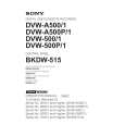
Interface test between search dial and dial interface is executed. 1. Press the F8 key to enter the menu. 2. Confirm the display on the EL panel as follows: Dial data : The numeral changes when the dial is turned. �2Ah� is displayed when the dial is fully turned to right and left. �0h� is displayed when the dial is in the center position. Dial direction : The arrow changes when the dial is turned.�8� is displayed when the dial is on the right of the center click position. �7� is displayed when the dial is on the left of the center click position. JOG/SHUTTLE sensor : JOG is displayed when the dial is pressed. SHUTTLE is displayed when the dial is released. Dial mode sensor : Fix the panel to the 90-degree position, loosen the screw shown in the figure at the back of the dial, and move the mode selection plate. The current display then changes to BETACAM/D-2.
4-3-4. Key Test
Rubber key, illumination switch, illumination switch LED, and other LED tests are executed. 1. Press the F7 key to enter the menu. 2. Press each key sequentially according to the display on the EL panel. 3. Confirm that the buzzer sounds when the key is pressed. Confirm that the switch lights and the buzzer sounds when the illumination key is pressed. 4. Message �Key TEST passed.� is lastly displayed on the EL panel. The test is completed at that time. If abnormality occurs in the key during operation, no sound is generated when the key was pressed. The test can be executed no longer. To terminate the test halfway, press the SHIFT and CLR keys simultaneously.
Lower control panel
A portion Search dial
Mode selection plate B3�14
BKDW-515
4-3
|
|
|
> |
|