|
There are currently no product reviews.
 ;
Excellent!! Got what I need and very fast!! Thank You
;
Manual acquired with good resolution, complete in all its pages, very good policy of the folder where are saved all products purchased.
 ;
Service manual very complete and clear. It was very helpfull for my work.
;
This is the 2nd time I download manuals from this website and I can say it's what I was expecting. It contains schematic, layout (decent quality), short description, parts and dissasembly instructions. I recomend it for anyone who wants to repair/modify this device.
;
Very useful Service Manual! With it I was able to identify the damaged pots in my old amplifier, purchase the adequate replacements and make myself the repair.
I have again my old amplifier, still a very good one that I will keep for as many years as I can!
Thanks to Owner Manuals!
1-2. Using the Extension Boards
1-2-3. Using the EX-667 Board
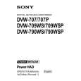
The EX-667 board is intended for check of the following boards/part: . SV-210 Board . DC-DC Converter . DIF-75 Board (BKDW-702) n The coaxial cable fixed on the EX-667 board is used for extending the DIF-75 board. SV-210 Board 1. Pull the SV-210 Board out. 2. Insert the EX-667 board into the slot, and then push it to connect the MB-811 board. 3. Connect the SV-210 board to the EX-667 board.
DC-DC Converter 1. Pull the DC-DC Converter out. 2. Insert the EX-667 board into the slot, and then push it to connect the MB-811 board. 3. Connect the DC-DC converter to the EX-667 board.
MB-811 board
EX-667 board
DC-DC converter
MB-811 board
EX-667 board
SV-210 board
1-6
DVW-790WS/709WS/707 DVW-790WSP/709WSP/707P P2V1
|