|
|
|
Categories
|
|
Information
|
|
Featured Product
|
|
|
 |
|
|
There are currently no product reviews.
 ;
The manual describes this product very good. It has the basic things to know and also a more detailed look. Very well made!
;
An excellent document to assist in the repair of my old personal tape player. It includes full circuit diagrams and physical layout drawings and full instructions on disassembly and fault finding.
Well worth the meagre price.
;
Very good conversation, Pretty fast Service, wood do it again,
Have paid by Paypal, so i got the Service Manual online after 15 Min.
Very helpfully.
Greeting from Germany,
Hans
;
Good-quality scans. Detailed description. I hope I can repair the machine.
;
High-quality scanning. Detailed description. Recommend for all technician. A+++
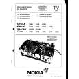
OVERALL BLOCK
Q19 MIX RV11 PEAKING RV10 PEAK OFFSET TP12 Q21 BUFF IC13 PEAKING CONT.
IC14(2/2) BLKG CLEAN
Q23 AMP
Q24 BUFF
Q25,Q26 CLAMP
Q22 BUFF
IC14(1/2) 6 5 3 RV12 SUB BRIGHT RV13 BRIGHT
7-13 8-13
7-6 8-6
IC7 1 C BLKG IC11(2/3) 18 V BLKG IC11(1/3)
7-7 8-7
4 2
TP10 +V DEF 5-1
11
SYNC SEP
8
7
V TRIG
V OSC 64
V DRIVER 2
1
Q7,Q8 V SAW GEN RV7 V SIZE TP11
-V DEF 5-2
7-5 8-5
RV6 V HOLD Q14 RV8 V LIN RV15 V SIZE(WIDE) TP2 DXF-701WS/701WSCE ONLY IC8,Q6,Q7 +9.5V REG 3 RV2 H SIZE 2 5 1
TP4 2 G1
7-10 8-10
1
V DY COIL
6-5 TP5
RV4 VH-ADJ 6-4 TP6
6-9 8-9
H1 4 3 H2 6-3
5
PICTURE TUBE
1
ANODE TP7 D12 3 G2 RECT 6-1 H DY 2 COIL
IC11(3/3) IC9 12 AFC RV5 H HOLD 13 14 H OSC H DRIVER 16 2 4 TP12 RV14 OP-ADJ Q8 Q9
4
6
IC10(2/2) 1 COMP 3
IC10(1/2) 7 BUFF 5
RV3 FOCUS
TP9 +H DEF 4-3 TP8 -H DEF 4-2 HLC
LED(A)
LED3 2-1 Q4 LED4 BUFF IC2 14 11 12 13 15 1 2 3 4 7 D2,Q2 BUFF 2-3 BUFF 10-3 LED5 REC/TALLY Q4 2-2 10-2 TAKE/GREEN 10-1 BATT
SHIFT REGISTER
IC3(1/2) IC5(1/2) IC3(2/2) Q3 BUFF LED6 3-1 IC4(1/2) IC1(3/3) 3-2 IC5(2/2) INV LED8 IC4(2/2) BUFF 3-3 11-2 REC(B) Q3 11-2 SHUTTER 11-1 LED7 GAIN UP
LED(B)
OVERALL BLOCK
B-DXF701WS-OABLOCK/M
DXF-701 (J, UC) DXF-701CE (CE)
4-2 4-3
|
|
|
> |
|