|
|
|
Categories
|
|
Information
|
|
Featured Product
|
|
|
 |
|
|
There are currently no product reviews.
 ;
It was just what I need to fix my old BMW's CD player. Very convenient also. Thank you.
;
Great Manual! It contains all the wiring schematics and mechanical exploded views that are essential for service and repair. I was surprised I even found this for such an old machine. Only wish I knew of this site many years ago.
;
Great manual very clear copied. You are making an incredible job. I appreciate a lot the rapidity and your efficiency. Thanks a lot
;
Good pdf of the service manual for this unit. Includes disassembly instructions, full schematics, board layouts, parts lists and diagnostic information. Some information is in the pdf twice (single pages, and split pages), but that could be how it was originally generated by panasonic, or perhaps the idea is to make it eaiser to put onto 8.5 x 11" pages.
Information was exactly what I needed. Delivery was overnight (less than 12 hours) and I was happy with the process.
;
5 STARS for FAST DELIVERY, BEST PRICES and QUALITY PRODUCT. Item was exactly as described with superb resolution. Will definitely source all my future requirements from this website. Thanks a lot owner-manual.com!
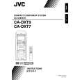
3.1.9 Removing the amplifier 1 and amplifier 2 boards (See Fig.17 to 19) [For DX-T9] � Remove the metal cover, tuner, fan, rear panel and main board. (1) (1)From the right side of the main body, remove the screw N attaching the earth wires to the bottom chassis. (See Fig.17.) Reference: After reassembling, fix the earth wires with the spacer as before. (See Fig.17.) (2) Disconnect the amplifier 2 board from the bridge board in the direction of the arrow while releasing the claw j of the connector CN200 on the bridge board. (See Fig.17.) (3) (3)From the left side of the main body, disconnect the card wire from the connector CN303 on the amplifier 1 board. (See Fig.17.) (4) Disconnect the amplifier 1 board from the bridge board in the direction of the arrow while releasing the claw k of the connector CN201 on the bridge board. (See Fig.18.) Note: When releasing the claws (j, k), take care not to break them. (See Figs.17 and 18.) Take out the amplifier 1 board and amplifier 2 board together from the main body. Remove the two screws P and remove the leaf spring. (See Fig.19.) Remove the two screws P and remove the amplifier 1 board from the heat sink. (See Fig.19.) Remove the four screws P and remove the amplifier 2 board from the heat sink. (See Fig.19.)
3.1.11 Removing the amplifier 1 and amplifier 2 boards (See Fig.17 to 19) [For DX-T5] � Remove the metal cover, tuner, fan, rear panel and main board. (1) From the right side of the main body, remove the screw N attaching the earth wires to the bottom chassis. (See Fig.17.) Reference: After reassembling, fix the earth wires with the spacer as before. (See Fig.17.) (2) Disconnect the amplifier 2 board from the bridge board in the direction of the arrow while releasing the claw j of the connector CN200 on the bridge board. (See Fig.17.) (3) From the left side of the main body, disconnect the card wire from the connector CN303 on the amplifier 1 board. (See Fig.17.) (4) Disconnect the amplifier 1 board from the bridge board in the direction of the arrow while releasing the claw k of the connector CN201 on the bridge board. (See Fig.18.) Note: When releasing the claws (j, k), take care not to break them. (See Figs.17 and 18.) (5) Take out the amplifier 1 board and amplifier 2 board together from the main body. (6) Remove the two screws P attaching the leaf spring and remove the amplifier 1 board from the heat sink. (See Fig.19.) (7) Remove the two screws P and remove the amplifier 2 board from the heat sink. (See Fig.19.)
(5) (6) (7) (8)
3.1.10 Removing the amplifier 1 and amplifier 2 boards (See Fig.17 to 19) [For DX-T7] � Remove the metal cover, tuner, fan, rear panel and main board. (1) From the right side of the main body, remove the screw N attaching the earth wires to the bottom chassis. (See Fig.17.) Reference: After reassembling, fix the earth wires with the spacer as before. (See Fig.17.) (2) Disconnect the amplifier 2 board from the bridge board in the direction of the arrow while releasing the claw j of the connector CN200 on the bridge board. (See Fig.17.) (3) From the left side of the main body, disconnect the card wire from the connector CN603 on the amplifier 1 board. (See Fig.17.) (4) Disconnect the amplifier 1 board from the bridge board in the direction of the arrow while releasing the claw k of the connector CN201 on the bridge board. (See Fig.18.) Note: When releasing the claws (j, k), take care not to break them. (See Figs.17 and 18.) Take out the amplifier 1 board and amplifier 2 board together from the main body. Remove the two screws P and remove the leaf spring. (See Fig.19.) Remove the two screws P and remove the amplifier 1 board from the heat sink. (See Fig.19.) Remove the three screws P and remove the amplifier 2 board from the heat sink. (See Fig.19.)
(5) (6) (7) (8)
1-18 (No.MB368)
 $4.99 DX-T5 JVC
Owner's Manual Complete owner's manual in digital format. The manual will be available for download as PDF file aft…
|
|
|
> |
|