|
|
|
Categories
|
|
Information
|
|
Featured Product
|
|
|
 |
|
|
There are currently no product reviews.
 ;
THANK YOU FOR A GOOD TRANSACTION, NICE COPY, CLEAR
;
Very Good! All the diagram are easy to read, and its complete.
;
This was an excellent source of detailed assembly information on a device which is at least 12 years old. A very lucky find, coupled with great service.
;
Excellent Service Manual and best price on the Internet. This Service Manual covers everything you could ever need including full circuit schematics, component layout diagrams, stripdown procedure and full parts list/breakdown. I needed this to carry out a modification to one of these headunits and this manual covered everything I needed. Fast delivery, processed within a few hours.
 ;
Thought I would never find a copy of the Technics SX-EN2 Service Manual until I found Owner-Manuals.com. Price was very fair and I received the download promptly. While a photocopy, it is quite readable and includes all the pertinent information and diagrams. Thank you Owner-Manuals!
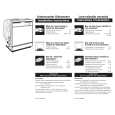
3.3.7 Removing the DVD pickup (See Figs.12 to 14) � Remove the tray assemblies, DVD servo board and DVD traverse mechanism assembly. (1) From the top side of the DVD traverse mechanism assembly, release the lock of the connector on the DVD pickup and disconnect the card wire in the direction of the arrow. (See Fig.12.) (2) Turn the screw shaft gear in the direction of the arrow 1 to move the DVD pickup in the direction of the arrow 2. (See Fig.12.) (3) Remove the screw G attaching the feed bracket and remove the feed bracket from the sections k. (See Fig.12.) (4) Release the claw m of the thrust spring in the direction of the arrow and remove the thrust spring. (See Fig.12.) (5) Remove the guide shaft from the sections (n, p) on the C.TM chassis. (See Fig.13.) (6) Remove the section q of the DVD pickup. (See Fig.13.) (7) Remove the two screws H attaching the rack arm spring and rack arm. (See Fig.14.) (8) Pull the guide shaft from the DVD pickup in the direction of the arrow. (See Fig.14.) 3.3.8 Attaching the DVD pickup (See Figs.12 to 14) (1) Attach the guide shaft to the DVD pickup and attach the rack arm spring and rack arm with the screws H. (See Fig.14.) (2) Attach the section q of the DVD pickup to the C.TM chassis first and attach the guide shaft to the sections (n, p). (See Fig.13.) Reference: When attaching the guide shaft to the section p, attach it under the rod spring. (See Fig.13.) (3) Attach the thrust spring and feed bracket with the screw G. (See Fig.12.) (4) Turn the screw shaft gear in the direction of the arrow 1 to move the DVD pickup in the direction of the arrow 2. (See Fig.15.) (5) Connect the card wire to the connector on the DVD pickup. (See Fig.15.)
DVD traverse mechanism assembly Thrust spring Connector
Feed bracket
2
G
1
k Screw shaft gear DVD pickup Thrust spring
m
Fig.12
DVD pickup
q
p Rod spring Guide shaft C.TM chassis
Fig.13
n
1-44 (No.MB531)
|
|
|
> |
|