|
|
|
Categories
|
|
Information
|
|
Featured Product
|
|
|
 |
|
|
There are currently no product reviews.
 ;
Excellent printing quality.
A complete and very usefull service manual with all details.
GREAT SERVICE AT VERY LOW PRICE!
A++
;
Excellent printing quality.
A complete and very usefull service manual with all details.
GREAT SERVICE AT VERY LOW PRICE!
A++
;
Excellent printing quality.
A complete and very usefull service manual with all details.
GREAT SERVICE AT VERY LOW PRICE!
A++
;
Excellent printing quality.
A complete and very usefull service manual with all details.
GREAT SERVICE AT VERY LOW PRICE!
A++
;
Excellent printing quality.
A complete and very usefull service manual with all details.
GREAT SERVICE AT VERY LOW PRICE!
A++
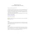
3.3.7 Removing the DVD pickup (See Figs.12 to 14) � Remove the tray assemblies, DVD servo board and DVD traverse mechanism assembly. (1) From the top side of the DVD traverse mechanism assembly, release the lock of the connector on the DVD pickup and disconnect the card wire in the direction of the arrow. (See Fig.12.) (2) Turn the screw shaft gear in the direction of the arrow 1 to move the DVD pickup in the direction of the arrow 2. (See Fig.12.) (3) Remove the screw G attaching the feed bracket and remove the feed bracket from the sections k. (See Fig.12.) (4) Release the claw m of the thrust spring in the direction of the arrow and remove the thrust spring. (See Fig.12.) (5) Remove the guide shaft from the sections (n, p) on the C.TM chassis. (See Fig.13.) (6) Remove the section q of the DVD pickup. (See Fig.13.) (7) Remove the two screws H attaching the rack arm spring and rack arm. (See Fig.14.) (8) Pull the guide shaft from the DVD pickup in the direction of the arrow. (See Fig.14.) 3.3.8 Attaching the DVD pickup (See Figs.12 to 14) (1) Attach the guide shaft to the DVD pickup and attach the rack arm spring and rack arm with the screws H. (See Fig.14.) (2) Attach the section q of the DVD pickup to the C.TM chassis first and attach the guide shaft to the sections (n, p). (See Fig.13.) Reference: When attaching the guide shaft to the section p, attach it under the rod spring. (See Fig.13.) (3) Attach the thrust spring and feed bracket with the screw G. (See Fig.12.) (4) Turn the screw shaft gear in the direction of the arrow 1 to move the DVD pickup in the direction of the arrow 2. (See Fig.15.) (5) Connect the card wire to the connector on the DVD pickup. (See Fig.15.)
DVD traverse mechanism assembly Thrust spring Connector
Feed bracket
2
G
1
k Screw shaft gear DVD pickup Thrust spring
m
Fig.12
DVD pickup
q
p Rod spring Guide shaft C.TM chassis
Fig.13
n
1-44 (No.MB531)
|
|
|
> |
|