|
|
|
Categories
|
|
Information
|
|
Featured Product
|
|
|
 |
|
|
There are currently no product reviews.
 ;
This service manual is a good copy of the original, complete and fully readable. It is really useful to repair my Tv set following its clear instructions.
 ;
Excellent quality. Easy process to download. No issues or problems at all - was exactly what I was looking for and needed. Great service.
;
I was having a hard time finding the problem with this Mackie 1604 unit. I didn't have a schematic. Went looking on the web and found your site and the price was more then reasonable. Ordered it and within the hour had the manual and within 15 minutes had the unit fixed. Best $4.99 I ever spent. Thank you.
Doug
;
This is a service manual in every sense of the word ( French and German versions of the text are included, as well as English..)
There are explanations of the mechanical and electrical functions, plenty of mechanical drawings, and the needed schematics. The quality of the scanning is excellent - all the component values are clearly legible - and very usefully there are pcb component layouts, so you can find a component on the schematic, and then very quicky pinpoint its physical location on the relevant pcb.
I cannot see how I can give this manual any less than the maximum 5 stars! Great value for money, which will pay for itself immediately. Excellent all round!
;
the manual is great and especially hard to find... thanks for the great service and having a hard to find manuel_
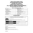
3.3.7 Removing the DVD pickup (See Figs.12 to 14) � Remove the tray assemblies, DVD servo board and DVD traverse mechanism assembly. (1) From the top side of the DVD traverse mechanism assembly, release the lock of the connector on the DVD pickup and disconnect the card wire in the direction of the arrow. (See Fig.12.) (2) Turn the screw shaft gear in the direction of the arrow 1 to move the DVD pickup in the direction of the arrow 2. (See Fig.12.) (3) Remove the screw G attaching the feed bracket and remove the feed bracket from the sections k. (See Fig.12.) (4) Release the claw m of the thrust spring in the direction of the arrow and remove the thrust spring. (See Fig.12.) (5) Remove the guide shaft from the sections (n, p) on the C.TM chassis. (See Fig.13.) (6) Remove the section q of the DVD pickup. (See Fig.13.) (7) Remove the two screws H attaching the rack arm spring and rack arm. (See Fig.14.) (8) Pull the guide shaft from the DVD pickup in the direction of the arrow. (See Fig.14.) 3.3.8 Attaching the DVD pickup (See Figs.12 to 14) (1) Attach the guide shaft to the DVD pickup and attach the rack arm spring and rack arm with the screws H. (See Fig.14.) (2) Attach the section q of the DVD pickup to the C.TM chassis first and attach the guide shaft to the sections (n, p). (See Fig.13.) Reference: When attaching the guide shaft to the section p, attach it under the rod spring. (See Fig.13.) (3) Attach the thrust spring and feed bracket with the screw G. (See Fig.12.) (4) Turn the screw shaft gear in the direction of the arrow 1 to move the DVD pickup in the direction of the arrow 2. (See Fig.15.) (5) Connect the card wire to the connector on the DVD pickup. (See Fig.15.)
DVD traverse mechanism assembly Thrust spring Connector
Feed bracket
2
G
1
k Screw shaft gear DVD pickup Thrust spring
m
Fig.12
DVD pickup
q
p Rod spring Guide shaft C.TM chassis
Fig.13
n
1-44 (No.MB531)
|
|
|
> |
|