|
|
|
Categories
|
|
Information
|
|
Featured Product
|
|
|
 |
|
|
There are currently no product reviews.
 ;
Perfect source for service manuals: fast and professional transaction; high quality, perfect readable and largely scaleable PDF; complete schemes, diagrams and spare part list. Tnx a lot, cu again!!!!
;
I got your link from a friend and I must say that I am really satisfied with your service. Specially this B&O manual I didn't find anywhere on the web... but you could deliver it :-) . You deliver very fast and the copy is of good quality. So your webpage is bookmarked. Thanks
;
This was the Sony CCU-500A Service manual I was looking for.
The price was reasonable.
The permission to download was quck.
I will use Owner-Manual.com for all my manual needs.
;
Excellent printing quality.
A complete and very usefull service manual with all details.
GREAT SERVICE AT VERY LOW PRICE!
A+++++++++++++++++++++++++
;
Excellent printing quality.
A complete and very usefull service manual with all details.
GREAT SERVICE AT VERY LOW PRICE!
A+++++++++++++++++++++++++
Troubleshooting > Procedure for Removing Disc from Faulty DVD Video Camera/Recorder
4-7 Procedure for Removing Disc from Faulty DVD Video Camera/Recorder
4-7-1 Item to be checked
Connect the AC adapter/charger or charged battery (power supply), make sure that the ACCESS indicator turns off, and then press the DISC EJECT button again. Even with normal product, the disc cannot be removed while the ACCESS indicator is lit or blinking. Information: Be sure to connect the AC adapter/charger or charged battery pack (power supply) before pressing the DISC EJECT button. The DISC EJECT button will not work unless a power supply is connected.
4-7-2 How to remove disc
If the disc cannot be removed after performing �4-7-1 Item to be checked�, remove it using the procedure in this section.
Cautions
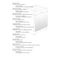
Laser light striking the eye may cause your eyesight to be lost: For safety, be sure to remove any power supply (AC adapter/charger, battery, etc.) from the DVD video camera/recorder before starting work. Information: 1) The DZ-GX20A is used for explanation in this section. Although the shapes of parts are slightly different for each model, the procedure is identical for all models. 2) Numbers in the procedural diagram are step numbers of procedure, and letters in brackets [ ] show the types of screw. 1) Remove screw [B]. 2) Remove the top cover in the direction of the arrow. 3) Use a fine-tipped flat-bladed screwdriver, etc. to move the lock slider in the direction of the arrow, and then open the disc cover. 4) After removing the disc, close the disc cover. When reassembling the removed parts, use the reverse procedure to removal.
Lock slider
3)
Accessory shoe 1) Screw [B] Top cover
2)
[B] M1.7�2.5 (Black)
Fig. 4-7-1 How to remove disc
4 - 43
|
|
|
> |
|