|
|
|
Categories
|
|
Information
|
|
Featured Product
|
|
|
 |
|
|
There are currently no product reviews.
 ;
THANK YOU FOR A GOOD TRANSACTION, NICE COPY, CLEAR
;
Very Good! All the diagram are easy to read, and its complete.
;
This was an excellent source of detailed assembly information on a device which is at least 12 years old. A very lucky find, coupled with great service.
;
Excellent Service Manual and best price on the Internet. This Service Manual covers everything you could ever need including full circuit schematics, component layout diagrams, stripdown procedure and full parts list/breakdown. I needed this to carry out a modification to one of these headunits and this manual covered everything I needed. Fast delivery, processed within a few hours.
 ;
Thought I would never find a copy of the Technics SX-EN2 Service Manual until I found Owner-Manuals.com. Price was very fair and I received the download promptly. While a photocopy, it is quite readable and includes all the pertinent information and diagrams. Thank you Owner-Manuals!
Troubleshooting > Procedure for Removing Disc from Faulty DVD Video Camera/Recorder
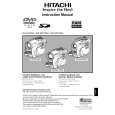
4-7 Procedure for Removing Disc from Faulty DVD Video Camera/Recorder
4-7-1 Item to be checked
Connect the AC adapter/charger or charged battery (power supply), make sure that the ACCESS indicator turns off, and then press the DISC EJECT button again. Even with normal product, the disc cannot be removed while the ACCESS indicator is lit or blinking. Information: Be sure to connect the AC adapter/charger or charged battery pack (power supply) before pressing the DISC EJECT button. The DISC EJECT button will not work unless a power supply is connected.
4-7-2 How to remove disc
If the disc cannot be removed after performing �4-7-1 Item to be checked�, remove it using the procedure in this section.
Cautions
Laser light striking the eye may cause your eyesight to be lost: For safety, be sure to remove any power supply (AC adapter/charger, battery, etc.) from the DVD video camera/recorder before starting work. Information: 1) The DZ-GX20A is used for explanation in this section. Although the shapes of parts are slightly different for each model, the procedure is identical for all models. 2) Numbers in the procedural diagram are step numbers of procedure, and letters in brackets [ ] show the types of screw. 1) Remove screw [B]. 2) Remove the top cover in the direction of the arrow. 3) Use a fine-tipped flat-bladed screwdriver, etc. to move the lock slider in the direction of the arrow, and then open the disc cover. 4) After removing the disc, close the disc cover. When reassembling the removed parts, use the reverse procedure to removal.
Lock slider
3)
Accessory shoe 1) Screw [B] Top cover
2)
[B] M1.7�2.5 (Black)
Fig. 4-7-1 How to remove disc
4 - 43
|
|
|
> |
|