|
|
|
Categories
|
|
Information
|
|
Featured Product
|
|
|
 |
|
|
There are currently no product reviews.
 ;
Very good quality. Some parts are not fully readable, but the fundamental ones are fine.
;
very good quality readable manual,printed off very well.
;
The manual was very accurate for the part that I was changing, I was able to order the correct part and had no issues with the replacement procedure. However, I was expecting to have more detailed repairs for the lower drive unit.
 ;
I needed the manual immediately and I got it immediately. I couldn't find this manual anywhere else on the net. The site was easy to traverse, and the price was very reasonable. I'll definitely be back for any future needs.
;
I received a good service manual, with good resolution. Improve the instructions for the purchase because they are not well understood.
For the rest, so good.
Thanks Angel.
ADJUSTMENT
Equipments required
Oscilloscope Frequency counter Test tapes, MTT-111N (0004 5032) and MTT-113N (0004 5033) Two 8-ohm resistors
Pre-adjustment procedure
1. Clean the head and all tape handling surfaces using standard cleaner and cotton swabs. 2. Connect an 8-ohm dummy load to headphone jack of each channel. 3. Set the main volume to the maximum. 4. Set the tape speed volume to the center position.
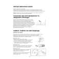
Head azimuth adjustment
Never use a magnetized screwdriver for this adjustment. The head azimuth adjustment screw is located just under the notch which can be seen when opening the cassette door. 1. Connect a oscilloscope to the dummy loads. 2. Set a tape MTT-113N holding the door open, and playback the tape. 3. By turning the adjustment screw slowly, adjust for amplitude of both channels at maximum and adjust for the waveforms in the same phase reading on the oscilloscope.
8-ohm Dummy Load OK Phone Jack EG-5 R-ch L-ch Ch 1 NG Ch 2
Oscilloscope
NG
8-ohm Dummy Load
< Figure 2 >
Tape speed adjustment
The tape speed adjustment volume VR32 is located on M370-MA3M PCB. 1. Connect a frequency counter to the dummy load. 2. Playback a test tape MTT-111N. 3. By turning the volume, adjust for 3000 Hz ± 30 Hz reading on the frequency counter.
8-ohm Dummy Load EG-5 Phone Jack Frequency Counter
< Figure 3 >
�7�
|
|
|
> |
|