|
|
|
Categories
|
|
Information
|
|
Featured Product
|
|
|
 |
|
|
There are currently no product reviews.
 ;
You can fully trust on this one!
All the schematics are very crear an in one piece per page
;
I have never bought a service manual which is as competely readable as this althogh it was a scanned pdf. Thank you for this succesful manual also cheaper than other sites.
;
Thanks for a very good and readable servicemanual. Just what I needed as a "dinosaur technician". I really recommmend this site and will come back.
Åsbjörn
;
The manual I purchased was just what I needed. I was glad to find a site where I can find so many manuals on a wide variety of products.
;
The best diagram that I used in a long time. Everything was right on te money. It was easy and fast. Iwoiuld but again when I need a service manual.
Entra Two Subwoofer
¤
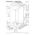
Cabinet (Not for sale) 2 6X 10 6X 8 6X 3
Amplifier (Not for sale)
7
8 10X
6 4X 9 4X 5 4
LEVEL
Min Max
LFE
NORMAL
PHASE
0º
180º
CROSSOVER FREQUENCY
50Hz 150Hz
L
LINE LEVEL IN
R
For LFE use L or R
REMOVE THESE TWO SCREWS TO REMOVE REAR COVER AND ACCESS AMPLIFIER
HIGH LEVEL IN
L
+
�
R L
HIGH LEVEL OUT
TO SERVICE THE ENTRA SUB TWO 1) Remove the grille. 2) Extract (6) rubber grille retainers as shown in the illustration above; this can be accomplished by carefully pulling them out of the cavities with long-nosed pliers or similar tool. 3) Remove the (6) Phillips screws that are now exposed. 4) Remove the front baffle. 5) Remove the (6) screws that secure the driver. 6) To service the amplifier, remove the (10) Phillips screws at the rear of the enclosure, and pull the amplifier out of the back. Remove the two Phillips screws as indicated in FIGURE A to remove the rear cover.
R
LONGER SCREW HERE
ON
POWER
OFF
120V 60Hz
Entra Sub Two
RISK OF ELECTRIC SHOCK DO NOT OPEN
CAUTION
Figure A
9
|
|
|
> |
|