|
|
|
Categories
|
|
Information
|
|
Featured Product
|
|
|
 |
|
|
There are currently no product reviews.
 ;
thanks you are the best.Very good detail, Quick service response. A useful service manual with all details.
;
Great service!!! Polecam gorąco wszystkim zainteresowanym
;
I liked the price plus it had everything i needed to service the tv.
thankyou Tim Hertz
;
The manual is excellent, well detailed, and divided into two parts. Received very quickly. Thank you.
;
a solid deal - quick and without any problems.
I life in europe - with downloads no loosing time
once again
8. Removing and replacing the LCD unit
1) Remove the four fixing screws cabinet . of the display unit from the top
9. Expansion RAM Board : UP-P02MB2
Make sure to save data before installing this option 1) Remove the top cabinet. 2) Install the Expansion RAM Board on the Main PWB. to the Option RAM connector
2
a) Insert the Expansion RAM Board aslant into the option RAM connector. b) Push the RAM disk unit Expansion RAM Board is locked by the arms of option RAM connector. It is possible to install one UP-P02MB2. Be careful of the direction of Expansion RAM Board to be installed. Install the Expansion RAM Board with the notch part of the PWB (Figure A) come right. Installing the Expansion RAM Board in the wrong direction may damage the connector part or make the machine out of order.
3
A 1
3
1
Fig. 5 2) Remove the two fixing screws unit. of the LCD unit in the display
3) The LCD unit is assembled with seven pawls. Remove the pawls in the order of to as shown in the figure.
LCD cabinet hear side
c
d
e
b
f
Fig. 7 3) Removing the Expansion RAM Board. a) Open the arms of option RAM connector right and left. b) The Expansion RAM Board will be lifted automatically.
a
g
10. RS232 I/F: ER-A7RS & EFT I/F: ER-02EF
4
1) Remove the rear cover. 2) Remove the two screws Fig. 6 3) Insert the I/F PWB from the shassis.
to the connector. .
4) Fix the I/F bracket to the shassis with screws 5) Install the ferrite core 6) Install the Nylon band . to the cables.
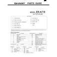 $4.99 ER-A770 SHARP
Parts Catalog Parts Catalog only. It's available in PDF format. Useful, if Your equipment is broken and You need t…
|
|
|
> |
|