|
|
|
Categories
|
|
Information
|
|
Featured Product
|
|
|
 |
|
|
There are currently no product reviews.
 ;
Although printing quality is not the best, the manual was very helpful in order to reactivate this ancient but still good electronic musical instrument.
 ;
as a first-time user and buyer from this site, i found the overall service outstanding!! this product is a godsend as, without it, i would never have been able to find my way around and use my machine as intended. i will certainly use this site again as required. many many thanx!!
;
This manual is exactly what I needed. This site always has every manual I need, and it is also much less expensive then most other sites. This is the only manual site I will use.
;
Useful manual, good scan, worth the pay if you find the unit difficult to operate.
;
Exactly as described, the full user-manual (145 pages). Perfect.
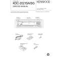
With Iron Wire: (1) Using desoldering braid, remove the solder from all pins of the flat pack-IC. When you use solder flux which is applied to all pins of the flat pack-IC, you can remove it easily. (Fig. S-1-3) (2) Affix the wire to a workbench or solid mounting point, as shown in Fig. S-1-5. (3) While heating the pins using a fine tip soldering iron or hot air blower, pull up the wire as the solder melts so as to lift the IC leads from the CBA contact pads as shown in Fig. S-1-5. (4) Bottom of the flat pack-IC is fixed with glue to the CBA; when removing entire flat pack-IC, first apply soldering iron to center of the flat pack-IC and heat up. Then remove (glue will be melted). (Fig. S-1-6) (5) Release the flat pack-IC from the CBA using tweezers. (Fig. S-1-6) Note: When using a soldering iron, care must be taken to ensure that the flat pack-IC is not being held by glue. When the flat pack-IC is removed from the CBA, handle it gently because it may be damaged if force is applied.
2. Installation
(1) Using desoldering braid, remove the solder from the foil of each pin of the flat pack-IC on the CBA so you can install a replacement flat pack-IC more easily. (2) The �I� mark on the flat pack-IC indicates pin 1. (See Fig. S-1-7.) Be sure this mark matches the 1 on the PCB when positioning for installation. Then presolder the four corners of the flat pack-IC. (See Fig. S-1-8.) (3) Solder all pins of the flat pack-IC. Be sure that none of the pins have solder bridges.
Example :
Pin 1 of the Flat Pack-IC is indicated by a " " mark.
Fig. S-1-7
Hot Air Blower
or
Presolder
Iron Wire
Soldering Iron To Solid Mounting Point Fig. S-1-5 CBA Fig. S-1-8 CBA Fine Tip Soldering Iron Flat Pack-IC
Flat Pack-IC Tweezers Fig. S-1-6
1-4-3
E5STA
|
|
|
> |
|