|
|
|
Categories
|
|
Information
|
|
Featured Product
|
|
|
 |
|
|
There are currently no product reviews.
 ;
Received downlink in less then 8 hours, Item was in good copy condition, and told me how to program the clock timer. The price was very resonable, and the process was very automated and was GREAT to work with.
;
Fast service, document is OK. Thanks! Searched for it long time.
 ;
I was very pleased with the manual I got for my amateur (ham) radio. Without it I could not figure out how to input and/or change the P/L setting on my radio. It drove me nuts as the radio was essentially useless. That all changed when my manual came. Then it took only minutes and I was done. Now my radio works fine. This is an exceptionally good resource as it's a very easy and user friendly download. Thank you very much! Dziękujemy za!
;
It answered my question, which was how to load the paper. I did notice that the very end of the manual was not visible.
;
The product manual I received was exactly what I was looking for, delivered painlessly at a very fair price. I can't ask for any more than that.
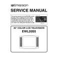
With Iron Wire: 1. Using desoldering braid, remove the solder from all pins of the flat pack-IC. When you use solder flux which is applied to all pins of the flat pack-IC, you can remove it easily. (Fig. S-1-3) 2. Affix the wire to a workbench or solid mounting point, as shown in Fig. S-1-5. 3. While heating the pins using a fine tip soldering iron or hot air blower, pull up the wire as the solder melts so as to lift the IC leads from the CBA contact pads as shown in Fig. S-1-5. 4. Bottom of the flat pack-IC is fixed with glue to the CBA; when removing entire flat pack-IC, first apply soldering iron to center of the flat pack-IC and heat up. Then remove (glue will be melted). (Fig. S-1-6) 5. Release the flat pack-IC from the CBA using tweezers. (Fig. S-1-6) Note: When using a soldering iron, care must be taken to ensure that the flat pack-IC is not being held by glue. When the flat pack-IC is removed from the CBA, handle it gently because it may be damaged if force is applied.
2. Installation
1. Using desoldering braid, remove the solder from the foil of each pin of the flat pack-IC on the CBA so you can install a replacement flat pack-IC more easily. 2. The ��� mark on the flat pack-IC indicates pin 1. (See Fig. S-1-7.) Be sure this mark matches the 1 on the PCB when positioning for installation. Then presolder the four corners of the flat pack-IC. (See Fig. S-1-8.) 3. Solder all pins of the flat pack-IC. Be sure that none of the pins have solder bridges.
Example :
Hot Air Blower
Pin 1 of the Flat Pack-IC is indicated by a " " mark.
Fig. S-1-7
or Iron Wire
Presolder
Soldering Iron To Solid Mounting Point Fig. S-1-5 Flat Pack-IC CBA CBA Fine Tip Soldering Iron Fig. S-1-8
Flat Pack-IC Tweezers Fig. S-1-6
3-3
TVN_SN
|
|
|
> |
|