|
|
|
Categories
|
|
Information
|
|
Featured Product
|
|
|
 |
|
|
There are currently no product reviews.
 ;
I am very pleased with the service manual for my RT-909. This was an easy purchase and great procuct, and much cheaper than other venues i had looked at. This web site is now listed in my favorites list. KEEP UP THE GOOD WORK. THANKS. J. BROWN
;
A very well written and easy to understand manual.
;
There was no problem at all.After paying i had to wait only a few hours,than i could
download the manual in best pdf-quality.
Thank You !
 ;
I found this service manual to be complete in every detail except for troubleshooting charts. It would be helpful if it had a set of troubleshooting charts; however it is a very good manual otherwise and for the price it is very well worth it.
;
Complete manual included schematics layouts and alignment procedure, clear to read and magnify, extremely pleased with manual and owner manual . com's service
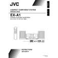
SECTION 3 DISASSEMBLY
3.1 Main body section 3.1.1 Removing the top cover (See Fig.1) (1) From the top side of the main body, remove the four screws A attaching the top cover.
A
Top cover
A
A
Fig.1 3.1.2 Removing the AL panel L and AL panel R (See Figs.2 to 7.) � Remove the top cover. (1) Remove the two screws B, screw C and screw C' attaching the bridge A. (See Fig.2.) Reference: When attaching the screw C' attach the lug wire with it. (See Fig.2.) (2) Remove the two screws C attaching the bridge B. (See Fig.2.) (3) Remove the screw C and screw C' attaching the bridge C. (See Fig.2.) Reference: When attaching the screw C' attach the lug wire with it. (See Fig.2.) From the back side of the main body, remove the three screws D attaching the bridge C. (See Fig.3.) From the top side of the main body, remove the two screws E attaching the AL panel L and AL panel R. (See Fig.4.) From the bottom side of the main body, remove the three screws F attaching the wood bar. (See Fig.5.) Remove the six screws G and two screws H attaching the AL panel L and AL panel R. (See Fig.6.) Remove the AL panel L and AL panel R in the direction of the arrow 2 while extending the back section of the AL panel L and AL panel R in the direction of the arrow 1. (See Fig.7.)
Bridge C Lug wire Bridge B
C'
C
C
C
(4) (5) (6) (7) (8)
C'
C
Bridge A
Fig.2
B
(No.MB150)1-7
 $4.99 EX-A1 JVC
Owner's Manual Complete owner's manual in digital format. The manual will be available for download as PDF file aft…
|
|
|
> |
|