|
|
|
Categories
|
|
Information
|
|
Featured Product
|
|
|
 |
|
|
There are currently no product reviews.
 ;
the manual is in good quality and it's in pdf. manual was send in less then 24h.
regards
mike
;
I would not plug this machine in without finding a manual like this. In addition to setup and normal operating instructions, it has troubleshooting flowcharts, diagrammed mechanical adjustments, and schematics to beat the band. The tech I hand it to would be thrilled to find solder side PCB diagrams with component outlines superimposed, pinouts for every IC chip, and line drawings of transistors, with labeled legs.
As for printing quality, this may be a copy of a copy, but even the finest print when enlarged is very legible. There is a bit of grayed print over a few pages, as if a wet page were placed over it, but the print is still very legible. If you could borrow an original manual and get it printed and bound for 4 to 6 times the cost, you could get better quality. In that case you wouldn't be here. For price, utility, and availability I am rating this manual highly.
;
I received the Manual in a timely manner and it was exactly what I needed.
This is a perfect copy of the Service Manual, The quality is great. I am very
happy. Thank you
;
exactly as they say. Within 24 hours the link to the pages and offcourse it was the right service manual. Super and thanks
 ;
The manual was exact the thing that was promised. My old car stereo is working again thanks to the information supplied.
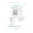
Level 3 Service Manual COSMO
3.c.1
Reception Block Diagram.
Mecha
GSM SUPPLY
SW
FL 504
TR504
FL 503
FL 500
FILTER
45 MHz
225 MHz GSM RX : 925 � 960 MHz
45 MHz
SW700
270 MHz
DCS RX : 1805 - 1880 MHz DCS SUPPLY
TR503 LNA
FL 502
FL 501
1/2
GSM & DCS :1080 MHz GSM & DCS : 540 MHz
1/2
RX I,Q
CLK SDATA SLE
IF PLL
1/2
IC602
1/2 90 MHz
DEMOD
RF PLL
RX GSM : 1150 - 1185 MHz RX DCS : 1580 � 1655MHz
TCXO 13 MHz
Description of Reception Block Diagram.
E-GSM band (925-960 MHz). Incoming RF signal from aerial is filtered and switched to the RX GSM path through SW700 . The signal is filtered by FL504 , before being amplified by TR504 , and is further filtered by FL503. Then, the signal input sent to RF-IC (IC600) in a first mixer stage. The RF signal (925-960 MHz) is mixed with the RF-PLL Frequency (1150-1185 MHz) coming from IC601 (PLLs & VCOs). For the channel 1, the output signal of the mixer is 225 MHz (1150 - 925 = 225 MHz), and is filtered by FL500. DCS band (1805-1880 MHz). Incoming RF signal from aerial is filtered and is switched to the RX DCS path through SW700 . The signal is filtered by FL501 , before being amplified by TR503 , and is further filtered by FL502. Then, the signal input to RF-IC (IC600) in a first mixer stage. The RF signal (1805-1880 MHz) is mixed with the RF-PLL Frequency (1580-1655 MHz) coming from IC601 (PLLs & VCOs) via IC602 (RF-VCO). For the channel 1, the output signal of the mixer is 225 MHz (1805 Mhz-1575 MHz = 225 MHz), and is filtered by FL500. For the E-GSM and DCS bands. The first intermediate frequency is 225 MHz. Then, this frequency is filtered by FL 500 before input to the second mixer stage. The first IF (225 MHz) is mixed with the 270 MHz (Fixed Frequency PLL 540 /2 = 270 MHz), to a second IF 45 MHz. The second IF is demodulated to Base Band (IC300) I/Q phase demodulated signals. RF-IC (IC600) provides automatic gain control. IC600 includes a quadrature demodulator. The second IF signal (45 MHz) is demodulated to I, Q balanced signals for One-C.
Version A Date: 04/00
12/29
Mitsubishi Electric Telecom Europe S.A. ZA le Piquet 35370 Etrelles Phone: +33 2 99 75 71 00 Fax: + 33 2 99 75 71 47
|
|
|
> |
|