|
|
|
Categories
|
|
Information
|
|
Featured Product
|
|
|
 |
|
|
There are currently no product reviews.
 ;
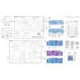
This is a high quality manual with clear schematic and components layout diagrams ; with service procedure included.
 ;
This service manual for the Kenwood KT-990D was reproduced really well ,is very legible and manual is complete.Combined with the low price paid,in the future,I will be checking Owner-Manuals.com any time I need a manual.
;
When I purchased this manual I had my doubts regarding the quality as the price was so reasonable as compared to other outlets.
The manual itself is of high standard the print is very clear as are the diagrams. Obviously with the diagrams one has to zoom in otherwise it is to small to be able to read.
Overall I am very pleased with the company who delivered as they said and with the manual they supplied.
I occasionally require a manual and now having registered with this company I shall order from them in the future.
;
I was at first dubious about payiong for downloaded manuals but having done so, I was extremely impressed with quality of the two manual I ordered, well worth the small price I paid.
I would highly recommend these to my friends.
;
reasonable price for the schematic - the service is perfect, all as expected and pointed by instructions - good scan of the original plans - thank you!
1.1
ROM Cover, Battery ASSY* and Ribbon Shaft Stopper
(*FAX870MC/FAX-930/FAX-931/MFC970MC)
(1) Open the control panel ASSY to the front. (2) Pull up the lock levers and open the recording paper cover ASSY to the rear. (3) As shown below, insert the tip of the spring hook at the center or right half of the locking arm (when viewed from the front), then lift up the hook to release and move the ROM cover to the right. (4) FAX870MC/FAX-930/FAX-931/MFC970MC: To replace the battery ASSY (Ni-MH battery), plug the power cord of the facsimile equipment into a wall socket, disconnect the battery harness from the main PCB, and take out the battery ASSY from the main frame. Set a new battery ASSY and unplug the power cord. Disconnecting the battery harness with the power cord unplugged will lose the settings (e.g., calendar clock, voice messages, and received FAX data) stored in the RAM. If you do not need to replace the battery ASSY, take out the battery ASSY from the main frame and put it on the main PCB with the battery harness being connected.
IV - 5
|
|
|
> |
|