|
|
|
Categories
|
|
Information
|
|
Featured Product
|
|
|
 |
|
|
There are currently no product reviews.
 ;
Great scan but please note that it is entirely in GERMAN.
 ;
High quality scan of the manual, very quick and easy download and very important, a truly honest price. thanks
;
Minden rendben, de két megjegyzés, az ábrák nehezen kivehetők és a fizetés után 24 órát kell várni a letöltésre.
;
Manual correct, and complete. Downloads cleanly. Format of manual was presumably difficult to PDF to A4, but works reasonably well.
;
This was a hard to find manual. When I did find it , some sites wanted way too much for the file.
Owner-manual .com had it for a really reasonable price. Not only that but it was sent very quickly and was a quality scanned document, unlike some others I purchased from a different site.
Good job guys!!
Larry
4. Connect an oscilloscope to the TP304 (IC301 Pin 36) blue * output.
CONTRAST ADJUSTMENT
5. Connect an oscilloscope (CHl) to the TP305 (IC301 pin 34) green output and (CH2) to the TP (IC301 pin 36) blue output. 6. Turn RV309 (SUB CONT B) to adjust the blue gain so that the positive polarity red signal step wave coincides with the positive polarity green signal step wave on the oscilloscope. 7. Disconnect pin 46 from pin 33 of IC301, and pin 45 from GND. The positive polarity signal and the negative polarity signal may not simultaneously coincide due to the variation.(Figures a and b) In this case, adjust these signals to an average value. (Figure c)
Procedure: 1. Short between IC301 pin-46 and pin-33, and between pin-45 and GND. (Short them at the same time.) Picture will show the white- compressed picture. 2. Input the 5- to 16-step black and white wave (stairstep) of the pattern generator (75 Sz and 1 Vp-p) to the A/V IN jack (J301). 3. Connect an oscilloscope (DC range 1 V/ DIV) to the TP305 (IC301 pin 34) green output. 4. Adjust RV307 (BRIGHT control) so that the black level obtains - 3.8V (line K).
A : 3.8 !I O.lVp-p
Figure b
Figure c
Negative
u-W
polarity Positive
polarity VIF ADJUSTMENT
5. Adjust RV301 (contrast) so that the white line obtains the GND potential (line M) (A = 3.8 t O.lVp-p). � 6. Disconnect pin 46 from pin 33 of IC301, and pin 45 from GND.
Note: These adjustments are not performed usually. Never
touch CT201 of adjusting device. While, only when CT201 have been replaced, make the following simple adjustment.
- Simple adjustment -
WHITE
BALANCE
ADJUSTMENT
Note: When performing this adjustment, set the direct
current drift .adjustment so that the direct currents on each channel of the oscilloscope is stabilized, and use the oscilloscope in this condition. Procedure: 1. Short between IC301 pin-46 and pin-33, and between pin-45 and GND. (Short them at the same time.) Picture will show the white - compressed picture. 2. Input the 5- to 16-step black and white step wave (stair -step) of the pattern generator (75 Sz and 1 Vp-p) to the A/V IN jack (J301). 3. Connect an oscilloscope (CHl) to the TP305 (IC301 pin 34) green output and (CHZ) to the TP504 (IC301 pin 32) red output. 4. Turn RV308 (SUB CONT R) to adjust the red gain so that the positive polarity red signal step wave coincides with the positive polarity green signal step wave on the oscilloscope. -7-
Procedure: Input the monochromatic gradation .wave from EXT ANT IN jack (JlOl). Connect an oscilloscope to Q314 emitter. Adjust CT201 so that the synchro signal is maximum (VIF adjustment). Receive the broadcasts of 2 to 13ch, and check if the screen is colored after the synchronism is stopped with each channel.
To / make maximum (VIF adjustment)
synchro chip
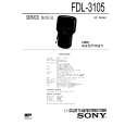 $4.99 FDL3105 SONY
Service Manual Complete service manual in digital format (PDF File). Service manuals usually contains circuit diagr…
|
|
|
> |
|