|
|
|
Categories
|
|
Information
|
|
Featured Product
|
|
|
 |
|
|
There are currently no product reviews.
 ;
Great price, Quick delivery, the document was very usefull A+++++++++++++++
;
Great price, Quick delivery, the document was very usefull A+++++++++++++++
;
Great price, Quick delivery, the document was very usefull A+++++++++++++++
;
Great price, Quick delivery, the document was very usefull A+++++++++++++++
;
Great price, Quick delivery, the document was very usefull A+++++++++++++++
8
8 screws as the plates withmm Secure shown. Use 6
screws for the holes marked with �A�, and 10 mm screws for the holes marked with �P�. Secure the screws in the order indicated by the numbers.
A4 A3 A3 P3 A4 A4 P4
Fixieren Sie die Platten wie in der Abbildung dargestellt mit den Schrauben. Verwenden Sie für mit �A� gekennzeichnete Löcher 6 mm Schrauben und 10 mm Schrauben für die mit �P� gekennzeichneten Löcher. Befestigen Sie die Schrauben in der Reihenfolge, in der sie nummeriert sind. Montieren Sie die rechte Seitenabdeckung des Geräts, indem Sie die Verbindungshaken in die entsprechenden �ffnungen einhängen. Befestigen Sie die längere Kassettenabdeckung an der rechten Kassettenseite, indem Sie die Verbindungshaken in die �ffnungen einhängen (zuerst oben, dann unten). Befestigen Sie die Schrauben der Seitenabdeckung des Geräts. Fixieren Sie die Kassettenabdeckung mit zwei 10 mm Schrauben. Montieren Sie die Stützplatte an die linke Geräteseite. Schieben Sie die oberen Enden der Stützplatte unter das Druckergehäuse. Stellen Sie sicher, dass die Führungen, wie in der Abbildung dargestellt, in die dafür vorgesehenen �ffnungen passen. Fixieren Sie die Platte, wie in der Abbildung dargestellt, mit den passenden Schrauben. Verwenden Sie für mit �A� gekennzeichnete Löcher 6 mm Schrauben und 10 mm Schrauben für die mit �P� gekennzeichneten Löcher. Befestigen Sie die Schrauben in der Reihenfolge, in der sie nummeriert sind. (In der rechten oberen �ffnung muss keine Schraube befestigt werden.) Montieren Sie die kürzere Kassettenabdeckung an die linke Kassettenseite, indem Sie die Verbindungshaken in die �ffnungen einhängen (zuerst oben, dann unten). Fixieren Sie die Kassettenabdeckung mit zwei 10 mm Schrauben.
Fissare le piastre con le viti come mostrato nella figura. Utilizzare viti da 6 mm per i fori contrassegnati da una �A� e viti da 10 mm per i fori contrassegnati da una �P�. Fissare le viti nell'ordine indicato dai numeri.
A2
A1
9 cover on the machine, Replace the right side
inserting the tabs into the holes.
Reinserire il coperchio laterale destro sul dispositivo, inserendo le linguette negli appositi fori.
9
Attach the longer cassette cover to the right side of the cassette, inserting the tabs into the holes (first top, then bottom).
1
Fissare il coperchio del cassetto di lunghezza maggiore al lato destro del cassetto, inserendo le linguette negli appositi fori (prima in alto, quindi in basso). Reinserire le viti nel coperchio laterale destro del dispositivo. Fissare il coperchio del cassetto con viti da 10 mm. Applicare la piastra di sostegno al lato sinistro del dispositivo, inserendo le estremità superiori della piastra sotto l'alloggiamento del dispositivo. Accertarsi che le guide si inseriscano nei fori come mostrato nella figura. Fissare la piastra con le viti come mostrato nella figura. Utilizzare viti da 6 mm per i fori contrassegnati da una �A� e viti da 10 mm per i fori contrassegnati da una �P�. Fissare le viti nell'ordine indicato dai numeri. Il foro superiore a destra non richiede l'applicazione di alcuna vite.
2
P
P
Replace the screws in the side cover on the machine. Secure the cassette cover with two 10 mm screws.
10
10
Attach the support plate to the left side of the machine, inserting the top edges of the plate under the machine housing. Make sure that the guides fit into the holes as shown. Secure the plate with screws as shown. Use 6 mm screws for the holes marked with �A�, and 10 mm screws for the holes marked with �P�. Secure the screws in the order indicated by the numbers. (Note that the top hole on the right does not require a screw.)
11 11
1
Attach the shorter cassette cover to the left side of the cassette, inserting the tabs into the holes (first top, then bottom).
Fissare il coperchio del cassetto di lunghezza minore al lato sinistro del cassetto, inserendo le linguette negli appositi fori (prima in alto, quindi in basso). Fissare il coperchio del cassetto con viti da 10 mm.
P P
2
Secure the cassette cover with two 10 mm screws.
12 12
Replace the rear cover (replace the screw under the small cover on the left side of the rear cover first, and then replace the small cover).
Montieren Sie die rückwärtige Abdeckung (fixieren Sie zuerst die Schraube unter der kleinen Abdeckung auf der linken Seite der rückwärtigen Abdeckung und dann erst die kleine Abdeckung).
Reinserire il coperchio posteriore (fissare prima la vite sotto il coperchio piccolo sul lato sinistro del coperchio posteriore, quindi reinserire il coperchio piccolo).
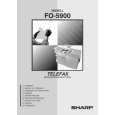 $4.99 FO5900 SHARP
Owner's Manual Complete owner's manual in digital format. The manual will be available for download as PDF file aft…
|
|
|
> |
|