|
|
|
Categories
|
|
Information
|
|
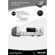
Featured Product
|
|
|
 |
|
|
There are currently no product reviews.
 ;
hat alles sehr gut geklappt. Das Servicemaual ist gut zu verwenden. Die Pläne und Schrift
ist klar und leserlich. Außerdem preiswert. Grüße an alle Hifi-Bastler
;
I got the manual quickly after the payment was transfered (1 day). The manual was exactly what i needed and the updates via e-mail were great. Thanx!
;
I've looked for this manual all over that internet, you guys had it and to a good price. A++++
;
I've looked some time for this manual, you guys had it and to a good price. A++++
 ;
factory technician level - complete with board views :
( removing chassis from cabinet , only thing missing ) ;
on weekends , staff is not available so - be patient .
3-1
3-1
DISMANTLING HINTS
Dismantling of Front Dismantling of mono board
1) Remove front . See picture 1 2) Remove whole front (disconnect the wires on the mono board coming from front)
Service position monoboard
1) Bring front in position as shown in picture 6 2) Snap nok of front in bottom to make front stable . See picture 7 3) Connect front wiring back to monoboard. *The tuner module doesn't have to be connected. Use an other source (pe.CD)
Power rod 1 snap 1 1
1
snap 2 2 2 2 3
picture 3 picture 7
2
3) Remove 14 x screws shown in mentionned aria . See picture 3
snap snap
picture 1
1) Remove top cover 2) Remove power rod 3) Remove 6 x screw as shown in picture 1 4) Release two snaps (left & right side front) 5) Release two snaps on the bottom side front 6) Tipp down front as shown in picture 2
cable-sleeve
picture 6
Service position main trafo
1
1
1
1
1
1 1
1 2
Metal bracket 1 1
picture 4
picture 2
4) Remove wires out the cable-sleeve. 5) Remove 7 x screw and remove metal bracket 6) Remove 2 x screw on mono board . See pictue 4 7) Remove mono board as shown arrow 1 & 2 . See picture 4 8) Bring the mono board in the service position as shown in picture 5
picture 9 1) Put main trafo as shown in picture 9
Handling service cover Dismantling of mainstrafo
1 1 1
1
1 1
1 1 1 1
picture 5
Legend
1 1
1
1
1
picture 10 picture 8 1 2 = Torx M3x6mm ( screw with big head ) = Torx 3x10mm 3 = Torx M3x6mm 1) To open the service cover cut 14 x lugs between cover and bottem . See picture 10 ( 2) To close the service cover put 11 x screw in mentionned holes. See picture 10 Service codenumber 12x Torx M3x6mm screw with big head = 4822 502 14659
PCS 102 488
1) Remove power rod 2) Remove 4x screw as shown in picture 8
)
|
|
|
> |
|