|
There are currently no product reviews.
 ;
has all the schematics you could need,and very well laid out format also has all part numbers along with an exploded view which is helpful
 ;
Very nice to have! Now it is no problem to understand how it is put together.
Helps me a lot.
;
good scans, all is clear. all pages in order. recommended
;
Très-très bon site, facile, très bon prix.
Au futur besoin, je n’hésiterais à faire appel à vous.
Merci
;
This is the correct service manual of SHARP RX-100H(BK) DAT.
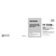
ADJUSTMENT -1/1
MAIN C.B
IFT1 1
Test point 1 531 4 Test point 2 42 R8
IC1 16pin L1 L3 TC2 L10
3
5
3
1. AM IF Adjustment Testpoint: IC1 (TA2104AN) 16PIN Adjustment location: IFT1 IFT1 ......................................................................... 450kHz 2. AM Frequency Range Adjustment Testpoint: R8 Set the frequency to be 530kHz and observe the test point voltage. It should be 0.9~1.2V. Change the frequency to be 1710kHz and observe the test point voltage. It should be less than 7 V. 3. AM Tracking Adjustment Testpoint: IC1 (TA2104AN )16PIN Adjustmentlocation:L10, TC2 L10........................................................................... 600kHz TC2 ........................................................................ 1400kHz
4. FM Frequency Range Adjustment Testpoint: R8 Adjustment location: L3 Setthe frequency to be 87.5 MHz then test the voltage. Adjust L3 so that test point voltage is 1.5 ± 0.05 V. Change the frequency to be 108 MHzand observe the test point voltage. It should be less than 4 V. 5. FM Tracking Adjustment Testpoint: IC1 (TA2104AN) 16PIN Adjustmentlocation: L1 L1............................................................................. 88MHz
-26-
|