|
|
|
Categories
|
|
Information
|
|
Featured Product
|
|
|
 |
|
|
There are currently no product reviews.
 ;
Very good conversation, Pretty fast Service, wood do it again,
Have paid by Paypal, so i got the Service Manual online after 15 Min.
Very helpfully.
Greeting from Germany,
Hans
;
Good-quality scans. Detailed description. I hope I can repair the machine.
;
High-quality scanning. Detailed description. Recommend for all technician. A+++
;
This is a good quality scan of the original Service Manual from Nordmende, Germany. Contains the circuit diagram, PCB layout, adjust/tune instructions as well. It is NOT in English but in GERMAN language! That was quite right for my german friend from the lower east side in Berlin.
 ;
Received via e-mail this PDF manual is worth the money. This is a quality scan of a manual in excellent condition and is just as good as having the original manual in hand. I have later seen the original manual and it was printed in colour, but this particular manual is black & white but scan resolution is high end quality! All drawings and pictures are presented in great detail. So, nearly perfect score in my opinion.
If you own the turntable you also should own the manual!
FS-M5
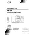
Removing the power board (See Figs. 16 and 17.)
Remove the left and right side panels. 1. Disconnect the wires from the connector CN901 on the power board. 2. Remove the tie bands bundling the wires. 3. Remove the screw M retaining the lug wire. 4. Remove the two screws N retaining the chassis . 5. Remove the power board by pinching the stud retaining the power board using radio pliers, etc.
Chassis Lug wire Tie bands Main board
Power transformer
Stud
CN901
N
Fig.16
M
Power board
Radio pliers, etc.
Power board Stud
Removing the main board (See Figs. 18 and 19.)
Fig.17 Remove the left and right side panels. Remove the top cover. Remove the front panel assembly. Remove the CD mechanism assembly. 1. From the inside of the rear panel, remove the five screws P retaining the bracket. 2. Remove the two screws Q retaining the speaker terminal of the main board. 3. Remove the solder from the soldered part e that attaches the FM antenna wire to the antenna board. 4. Remove the three screws R retaining the rear panel, then remove the rear panel. 5. From the top side of the main body, remove the screw S retaining the bracket of the main board. 6. Remove the screw T retaining the regulator IC(IC302). 7. Remove the tie bands bundling the wires. 8. Disconnect the wire from the connector CN901 on the power board. 9. Remove the stud on the main board, and then take out the main board from the chassis.
Soldered part e Heat sink
Chassis
P
P
R Q
Fig.18
R
Regulator IC Main board FM antenna wire (IC302) Antenna board T Stud
CN901
S
Power board Bracket Power transformer Tie bands
Chassis
Fig.19
1-10
 $4.99 FS-M5 JVC
Owner's Manual Complete owner's manual in digital format. The manual will be available for download as PDF file aft…
|
|
|
> |
|