|
|
|
Categories
|
|
Information
|
|
Featured Product
|
|
|
 |
|
|
There are currently no product reviews.
 ;
IF PRINTED CIRQUIT BOARD WIRING VIEW WAS ONE TONE LIGHTER, THEN 5 STAR RANK HAS TO BE MY CHOISE.
 ;
Very usefull, good quality drawings !
Muito útil encontrei todas as informações necessárias.
;
Wanting to repair a neighbours tape recorder I needed the necessary information, it makes it easier. Although the service manual is described as "Language : English" To my dismay I found that it is entirely written in German, a language I do not understand. At least I now have the schematics which will help of sorts. I may not use this service again due to the laguage difficulty after all when it states English you do not expect it to be entirely in another language.
;
GOOD SERVICE MANUAL.I ALWAYS BUY THERE IF I FIND WHAT I AM LOKING
;
Good quality (clearly readable) manual, I'm glad I could find it here, at a bargain price!
Service hints CAUTION
10-2
CHARGED CAPACITORS ON THE SERVO BOARD MAY DAMAGE THE CD DRIVE ELECTRONICS WHEN CONNECTING A NEW CD MECHANISM. THAT´S WHY, BESIDES THE SAFETY MEASURES LIKE � SWITCH OFF POWER SUPPLY � ESD PROTECTION ADDITIONAL ACTIONS MUST BE TAKEN BY THE REPAIR TECHNICIAN.
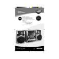
The following steps have to be done when replacing the CD mechanism: 1. Disconnect flexfoil cable from the old CD drive 2. Put a paperclip on the flexfoil to short-circuit the contacts (fig.1) 3. Remove the old CD drive 4. Remove paperclip from the flexfoil and connect it to the new drive 5. Position the new CD drive in its studs 6. Remove solder joint from the Laserunit
fig.1
Attention: The laser diode of this CD drive is protected against ESD by a solder joint which shortcircuits the laserdiode to ground. For proper functionality of the CD drive this solder joint must be removed after connection the drive to the set.
Emergency open
In case of a Supply fault, the tray can be opened manually. 1. Remove the top cover of the set to get access to the Changer Module. 2. Turn gearwheel clockwise (as shown in picture below).
|
|
|
> |
|