|
|
|
Categories
|
|
Information
|
|
Featured Product
|
|
|
 |
|
|
There are currently no product reviews.
 ;
Once again owner-manual.com has saved the day for me, and come through with the manual I need. I looked other places too, and couldn't find it anywhere. Thank You owner-manual.com!!! You're the BEST!
;
very good quality that can be magnified several times, and it remains readable.
For sure I will return next time the need for a service manual arise.
;
The service manual is really great - thanks to it I was able to install the laser unit and thus "save" my CD-player, which seemed to be impossible before I had the manual.
;
Downloaded the Service manual OK of the Technics Piano and have now repaired it and its going fine. Excellant; thank you for the fine servce. A.M
 ;
This site is working fine! Did buy a manual for SX-EX25L and after a while I could download it and fix the problem. Nice and easy!
2-2
2-2
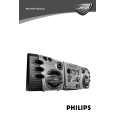
DISMANTLING INSTRUCTIONS
Dismantling of the Front Control Board and Front Display Board Dismantling of the Front Control Board and Front Display Board
1) The Knob Volume Rotary (pos 164) can be remove by pulling it out in the direction as shown in Figure 8. 2) The Knob Game Sound Control (pos 176) can be remove by pulling it out in the direction as shown in Figure 9.
3) Loosen 4 screws D (see Figure 11) to remove the Bracket PCB Front Display (pos 183) and Front Display Board (pos 1101-A). 4) Loosen 1 screw E (see Figure 12) to remove the IR Eye Board (pos 1107-H). 5) Loosen 2 screws F (see Figure 12) to remove the ECO Power Board (pos 1107-E). 6) Loosen 3 screws G (see Figure 12) to remove the Bracket VU Meter 2 (pos 136) and loosen 2 screws H to remove the VU Meter Right Board (pos 1107-D) from the Bracket VU Meter 2. 7) Loosen 3 screws J (see Figure 12) to remove the Bracket VU Meter 1 (pos 129) and loosen 2 screws K to remove the VU Meter Left Board (pos 1107-C) from the Bracket VU Meter 1.
11) Loosen 3 screws P (see Figure 14) to remove the Game Port Board (pos 1107-G).
12) Loosen 2 screws Q (see Figure 15) to remove the USB LED Board (pos 1107-F).
Figure 12
Figure 8 8) Loosen 2 screws L (see Figure 13) to remove the USB PC LINK Board (pos 1104). 9) Loosen 9 screws M (see Figure 13) and loosen the 2 nuts (see Figure 10) to remove the Front Control Board (pos 1107-A). 10)Loosen 1 screw N (see Figure 13) to remove the Headphone Board (pos 1107-B). Figure 13
Figure 9
Figure 10
Figure 11
Figure 14
Figure 15
|
|
|
> |
|