|
|
|
Categories
|
|
Information
|
|
Featured Product
|
|
|
 |
|
|
There are currently no product reviews.
 ;
- Very good scan quality, PERFECT!
- Sehr gute scan Qualitaet, empfehlenswert!
Wolfgang Sundhaus
 ;
Good site, works ok and you get what you order, no problems experienced, got my manual within a day. A++++
;
Original well scanned manual. Got the job done. Microwave problem found & corrected. For $5 and a new magnitron from ebay, it was a cheap and good the first shot fix. Electrical schematics allowed me to mage sure every thing else was ok before cutting and order for parts. Hard to live without.
;
I was very skeptical of this website, I have never downloaded manuals before. I put it on the AMEX and payed through Paypal to ensure protection. I got the manual exactly as described and now I can replace the filter capacitor for this amp. Great Price, others selling for 12.99 or more and this is the same manual. I will search out this website for other manuals. Thank you
;
Manual was reasonably easy to follow. I am not an engineer or know much about electronics but with the manuals help I was able to figure out the problem, identify the part required for the repair. Replacement part cost around $30. Whilst replacing the part I was telling myself, "this aint gonna work cos it seems far too easy". Took about 15 minutes to do and my plasma TV works a treat. Would never have been able to do this without the service manual.
1.3.2 Disassembly method ( I )
STEP 1 2 PART NAME FRONT CASE REAR CASE OPERATION UNIT FIG. NO. POINT Remove screws 2 (115), 3 (156), 4 (157), 1 (154) Remove the Connector r MAIN CN4001 OPERATION UNIT Remove the TOP COVER 3 STROBE BOARD ASSEMBLY Fig 1-3-1 Remove the Connector n MAIN CN6601 STROBE CN6501 Remove the Connector p MAIN CN5501 JACK CN101 m LCD MODULE (BL) JACK CN701 Remove screws 3 (116) 2 (115) Remove screw 1 (114) Remove screws 2 (114) e (SD3), f (SD4), g (SD5) Note 1 Note 3 Note 4 Note 1 Note 1 Note 2 Note 1 NOTE
Fig 1-3-1
JACK BOARD ASSEMBLY
4
LCD MODULE
Remove the Connector Remove screws k MAIN CN3002 LCD MODULE (LCD) 2 (114) Fig 1-3-2 Remove from the Frame Assy Remove from the LCD Holder Remove the Connector h MAIN CN501 OP UNIT c MAIN CN3001 MON/REG CN9001 d MON/REG TL9001 Frame Assy Remove the PWB HOLDER Remove from the Frame Assy
5
MAIN BOARD ASSEMBLY
MONI/REG BOARD ASSEMBLY 6 OP UNIT Fig 1-3-3
d (SD1) Remove screws 2 (114) Remove screws 3 (117)
Note 1
CONNEC- NO.OF TOR/HL PINS c d e f g h j k m n p q r s t u v w x 80 1 1 1 1 22 2 24 2 14 38 28 12 1 1 1 1 1 1 MAIN Board CN3001
CONNECTION MONI/REG Board CN9001 MAIN FRAME (RED) MAIN FRAME (BROWN) MONI/REG Board J9001 (BLACK) MONI/REG Board J9002 (RED) OP UNIT OP UNIT LCD MODULE (LCD) LCD MODULE (BL) STROBE Board CN6501 JACK Board CN101 CCD Board CN1001 OPERATION UNIT STROBE Board J6501 (Through hole) STROBE Board J6502 (Through hole) STROBE Board J6503 (Through hole) STROBE Board J6504 (Through hole) STROBE Board J6505 (Through hole) STROBE Board J6506 (Through hole)
Note 1 Destination of connectors. Note: Three kinds of double-arrows in connection tables respectively show kinds of connector/wires.
MONI/REG Board TL9001 JACK Board TP3 JACK Board TP2 JACK Board TP1 MAIN Board CN501 MAIN Board CN502 MAIN Board CN3002 JACK Board CN701 MAIN Board CN6601 MAIN Board CN5501 MAIN Board CN2001 MAIN Board CN4001 STROBE UNIT WIRE (ORANGE) STROBE UNIT WIRE (BROWN) STROBE UNIT WIRE (RED) STROBE UNIT WIRE (BLACK) STROBE UNIT WIRE (Red, Thin wire) STROBE UNIT WIRE (BLACK, Thin wire)
: Board to Board connector : Flat wire : Wire
Note 2 Be careful from electric shock hazard because the capacitor (C6512) for the strobe is exposed. Be sure to positively discharge the capacitor if it is energized by short-circuiting a resistor (10 - 22 k ) connected at both capacitor terminals. Please be very careful when doing this job. Note 3 Make sure that there is no slippage between the LCD panel and the backlight, the four spots are locked with hooks securely, and the sheet is placed in the correct direction. no slippege 4 sprts locked
Note 4 Both the stripe pattern and the non-slippage (notch) on the sheet surface are to be in the direction as illustrated.
1-3
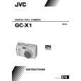 $4.99 GCX1E JVC
Owner's Manual Complete owner's manual in digital format. The manual will be available for download as PDF file aft…
|
|
|
> |
|