|
|
|
Categories
|
|
Information
|
|
Featured Product
|
|
|
 |
|
|
There are currently no product reviews.
 ;
I was very satisfied with the service manual I ordered and downloaded. I will definitely buy again from this seller.
;
Great product. Recieved it fast...exactly as advertised.
;
Manuals were delivered promptly and were correct as advertised. No issues with the download link which was provided promptly after everything was processed. Very pleasant experience
;
Paid for service manual & got the download fast - worth a visit if you need a service manual
;
It's the manual, I am searching for. Now I am able to repair my Braun A501.
5
6
7
8
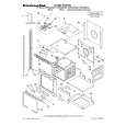
Removing the Amp Unit (Fig. 3)
Amp Unit
Heat Sink
A
1 Remove six black screws (M3 x 10). 2 Remove six white screws (M3 x 12). A Screw holes in the PCB are printed with
numbers 1 to 12. Remove screws in numerical order. Re-assembly takes the reverse order of disassembly. Caution) The Amp Unit is adhered on the Heat Sink with silicon grease. This means forcibly removing the Amp Unit from the Heat Sink may break the PCB.
1
1 3
1
2
2
2
B
2
2 3
2 1
1
1
3
Remove all of the twelve screws. Then, remove the two black screws (M3 x 5). Tighten screws whose length is M3 x 8 or more into the two screw holes so as to raise the Amp Unit above the Heat Sink. Then, remove the Amp Unit. (Since screw threads differ, 1 and 2 screws cannot be used.)
C
Fig. 3
Caution when re-assembling the Amp Unit and the Heat Sink
Be aware that the RCA Terminal may break unless the Amp Unit and the Heat Sink are assem-bled following the correct procedures given below. 1) Secure the RCA-side Panel on the Heat Sink with screws. (Fig. 2) 2) Place the Amp Unit on the Heat Sink aligning with two studs. (Fig. 4) 3) Move the Amp Unit until the RCA Holder on the Amp Unit comes in contact with the inside of the Panel. (Fig. 4) Caution in steps 2) and 3) When you place the Amp Unit on the Heat Sink, you will find no positioning marks to determine the direction of two panels. To position them correctly, the Amp Unit needs to be moved to the place where it comes in contact with the RCA-side panel. If you do not position them, an excessive force can be applied to the RCA Terminal. This may result in breakage. 4) Secure the RCA-side Panel and the RCA Holder with screws. (Fig. 2) 5) Secure the Amp Unit on the Heat Sink with screws. (Fig. 3) 6) Secure the Panel for the Power Terminal side in place with screws. (Fig. 2)
RCA Holder
RCA Terminal (CN111)
Amp Unit
D
A
Move the Amp Unit
E
Heat Sink Panel for the RCA side Stud Stud
Fig. 4
F
GM-5100T/XU/EW
27 7 8
5
6
|
|
|
> |
|