|
|
|
Categories
|
|
Information
|
|
Featured Product
|
|
|
 |
|
|
There are currently no product reviews.
 ;
As Always you can find here manuals even of difficult TV scheme which are scan in almost perfect way.clear and fast!!!!!
Great work thanks!
;
Incredibly clear!!!! Well done, complete and wonderful. It could not better than this!!!!
 ;
Thank You for fast delivery for the sheme.
Everything allright.
Thanks & best regards Franz
;
again you did a very good job. It was fast too. Photocopy are really readable and clear
;
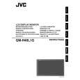
Probably it never existed a 1081 official service manual from Commodore, it's look more like a NAPCEC service manual & diagrams compilation of the 1084 series and his variants, like the nap6523, 8cm505, 1084S, 1084P and obviously the 1081. It's more complete than other scans and the quality of the scans also are far superior. It has two circuit diagrams variants of the 1081, mono and stereo versions. It doesn't include a diagram for the Philips CM8500 or CM8501, they look like the 1081 but they are slightly different.
3.2.13 REMOVING THE TEMP PWB (Fig.2) � Remove the REAR COVER. (1) Pull out the TEMP PWB from the claw of the TOP FRAME. 3.2.14 REMOVING THE CONTROL PWB (Fig.2) � Remove the REAR COVER. (1) Remove the 2 screws [A]. (2) Remove the CONTROL KNOB. (3) Remove the CONTROL PWB from the TOP FRAME. 3.2.15 REMOVING THE CHASSIS BASE AND TOP FRAME (Fig.2) � Remove the REAR COVER. � Remove the BACK SHIELD. � Remove the SIDE SHIELD. � Remove the TERMINAL BRACKET. � Remove the BACK BRACKET. (1) Remove the 2 screws [B]. (2) Remove the CHASSIS BASE. (3) Remove the 2 screws [C] and the 2 screws [D]. (4) Remove the TOP FRAME. 3.2.16 REMOVING THE LED PWB (Fig.2) � Remove the REAR COVER. � Remove the BACK SHIELD. � Remove the SIDE SHIELD. � Remove the TERMINAL BRACKET. � Remove the BACK BRACKET. � Remove the CHASSIS BASE. � Remove the TOP FRAME. (1) Remove the 1 screw [E]. (2) Remove the LED PWB. 3.2.17 REMOVING THE LCD PANEL UNIT (Fig.2) � Remove the REAR COVER. � Remove the BACK SHIELD. � Remove the SIDE SHIELD. � Remove the TERMINAL BRACKET. � Remove the BACK BRACKET. � Remove the CHASSIS BASE. � Remove the TOP FRAME. (1) Remove the 2 screws [F] and the 2 screws [G]. (2) Remove the BOTTOM FRAME. (3) Remove the LCD PANEL UNIT from the FRONT PANEL.
1-14 (No.YA347)
|
|
|
> |
|