|
|
|
Categories
|
|
Information
|
|
Featured Product
|
|
|
 |
|
|
There are currently no product reviews.
 ;
I was very glad recieving the service manal from You. Additionaly very fast. Extremaly nice servicing. Thanks very mach! Now my GX-220 working better, than it was made. Alexander from Moscow, Russia/
;
Sweet! I won the item on eBay and couldn't adjust the geometry or even keep a steady picure. This guide has the full schematics (not available anywhere else as far as I could tell), and was a bargain for the wealth of knowledge it contains. I hooked it up to my testing equipment, tweaked a few potentiometers and got it playing videogames in no time. Thanks!
;
It was just what I need to fix my old BMW's CD player. Very convenient also. Thank you.
;
Great Manual! It contains all the wiring schematics and mechanical exploded views that are essential for service and repair. I was surprised I even found this for such an old machine. Only wish I knew of this site many years ago.
;
Great manual very clear copied. You are making an incredible job. I appreciate a lot the rapidity and your efficiency. Thanks a lot
GM-X1024,GM-X924
7.2 DISASSEMBLY
Panel Unit
A A B B B A A A A A A B B
- Removing the Case and the Panel Unit
1. Remove eight screws A, seven screws B and two screws C. 2. Remove Case and Panel Units.
C B
Case
B C
Panel Unit
Fig. 13
D
B LPF/HPF PCB A LPF/HPF PCB
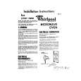
- Removing the Heat Sink
Some silicone glue has been applied between the Heat Sink and the Heat Sink(Sub). therefore, to remove the Amp Unit from the Heat Sink. 1. Remove two screws D.
D
F F F F
F
Heat Sink(Sub)
E E
F
F F E
2. Remove A LPF/HPF PCB and B LPF/HPF PCB. 3. Remove four screws E and eight screws F. 4. Use 2 pcs. of screw E and insert them into the two holes marked with an arrow. 5. Alternately tighten them little by little until the Heat Sink(Sub) separates from the Heat Sink.
E
Heat Sink(Sub) Amp Unit Heat Sink
Fig. 14
27
|
|
|
> |
|