|
|
|
Categories
|
|
Information
|
|
Featured Product
|
|
|
 |
|
|
There are currently no product reviews.
 ;
Found the quality of the copy excellent and a very quick service. I would certainly recommend the service.
;
Good quality, clear diagrams. Exactly what I needed.
 ;
Good product. All the information is invcluded, but due to the complexity of the amplifier, it still is difficult to get it to operation again.
;
Very professional seller; very fast, accurate and rielable service.
;
great works fine, got the manual on mail within a day
GM-X1024,GM-X924
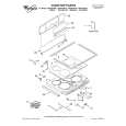
7.2 DISASSEMBLY
Panel Unit
A A B B B A A A A A A B B
- Removing the Case and the Panel Unit
1. Remove eight screws A, seven screws B and two screws C. 2. Remove Case and Panel Units.
C B
Case
B C
Panel Unit
Fig. 13
D
B LPF/HPF PCB A LPF/HPF PCB
- Removing the Heat Sink
Some silicone glue has been applied between the Heat Sink and the Heat Sink(Sub). therefore, to remove the Amp Unit from the Heat Sink. 1. Remove two screws D.
D
F F F F
F
Heat Sink(Sub)
E E
F
F F E
2. Remove A LPF/HPF PCB and B LPF/HPF PCB. 3. Remove four screws E and eight screws F. 4. Use 2 pcs. of screw E and insert them into the two holes marked with an arrow. 5. Alternately tighten them little by little until the Heat Sink(Sub) separates from the Heat Sink.
E
Heat Sink(Sub) Amp Unit Heat Sink
Fig. 14
27
|
|
|
> |
|