|
|
|
Categories
|
|
Information
|
|
Featured Product
|
|
|
 |
|
|
There are currently no product reviews.
 ;
Good service manual,i saved from scrapping this deck,is now fully functional.Thanks.
 ;
Found this to be the manual included with the original packinging, was helpfull but did not give any detailed repair instructions.
;
Complete service manual, was very helpful in repairing this tapedeck.Thanks.
;
The service manual was a copy of the original from Wirlpool. The quality was good, all neccecary information was available including the service-codenumbers, so I could order the right part to be replaced for repair.
Downloding was no probem after the payment.
Thanks for the service!
;
Good,readable manual. I found other manuals that were not readable when it came to part ID, but the one downloaded from owner-manual.com was better than expected. I will do buisness with owner-manual.com again.
GM-X422, GM-X322
7. GENERAL INFORMATION
7.1 DISASSEMBLY
A
- Removing the Case and Panel
1. Remove six screws A, and then remove case. 2. Remove panel.
A
Panel
Case
Fig. 6
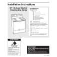
- Removing the Amp Unit
B C
Sub Heat Sink
Some silicone glue has been applied between the Heat sink and the Sub Heat Sink. therefore, to remove the Amp Unit from the Heat Sink. 1. Remove four screws B and Three screws C. 2. Use 2 pcs. of screw B and insert them into the two holes marked with an arrow. 3. Alternately tighten them little by little until the Sub Heat Sink separates from the Heat Sink.
C
B
Sub Heat Sink Amp Unit Heat Sink Fig. 7
15
|
|
|
> |
|