|
|
|
Categories
|
|
Information
|
|
Featured Product
|
|
|
 |
|
|
There are currently no product reviews.
 ;
Very pleased with the quality of the scan. No complaints whatsoever.
 ;
I liked the product. I would use their sevices again.
;
I Recently purchased yet another Service Manual from Owner-Manuals.com, this time for a Sony EVS700ES/UB Videocassette Recorder. The Manual was available for upload within two hours and is an Extremely Good copy, as some of this I was able to enlarge to get even better detail.
Once Again, Very happy with the result!
;
A good and useful manual. With these, We was abled to isolate and pin point the component that was causing the problem. The total time spent in troubleshooting is very much reduced.
;
The quality of the manual is top. The transfer worked perfect and fast.
No problems at all. Recommendable
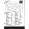
Connection Diagram SPECIFICATIONS
Fuse (30 A)
Grommet
Fuse (30 A) Dimensions . 255 (W) 61 (H) � 310 (D) mm Ground wire (black) [RD-223] (sold separately). . [10 (W) 2-3/8 (H) � 12-1/4 (D) in.] Connect to metal body or chassis. Weight . 4.1 kg (9.0 lbs.) (Leads for wiring not included) Maximum power output . 100 4 / 240 W � 2 (EIAJ) Continuous power output 50 W � (at 14.4V, 4 �, 20 � 20,000 Hz, 0.08% THD) . 120 W � 2 (at 14.4V, 4 �, 20 � 20,000 Hz, 0.8% THD) RCA input jacks Load impedance . 4 (1 � 8 � allowable) Connecting wires with RCA . (Bridge connection: 2 � 8 � allowable) Frequency response . 10 � 50,000 Hz (+0 dB, �1 dB) pin plugs (sold separately). Signal-to-noise ratio . 105 dB (IHF�A network)
Power source . 14.4 DC (10.8 � 15.1 V allowable) Grounding system . Negative type Special red battery wire [RD-223] (sold separately). Current consumption . 29 A (at continuous power, 4 �) After making all other connections at the amplifier, Average current drawn* . 8 A (4 � for four channels) connect battery wire terminal of the amplifier to . 12.5 A (4 � for two channels) positive (+) terminal of the battery. Fuse . 20 A � 2
RCA input Amplifier with . 60 W � 4 (at 14.4V, 2 �, 20 � 20,000 Hz, 0.8% THD)
Car stereo with Distortion . 0.004% (10 W, 1 kHz) Separation . 70 dB (1 kHz) RCA output jacks
External Output Low pass filter . Cut off frequency: 50 � 120 Hz For details on how connect to . Cut off slope: �12 dB/oct RCA input jacks A and B, see the High pass filter . Cut off frequency: 50 � 120 Hz �Connecting the Speakers and Input . Cut off slope: �12 dB/oct wires� section. Input level / impedance . RCA: 0.4 � 4.0 V/22 k� If only one input plug is used, do not . Speaker: 1.6 � 10 V/78 k� connect anything to RCA input jack B. Note: � Specifications and the design are subject to possible modification without notice due to improvements.
output RCA input jack A, B � The average current drawn is nearly the maximum cur-
*Average current drawn Reverse
rent drawn by this unit when an audio signal is input. Use this value when working out total current drawn by multiple power amplifiers.
Connecting wires with RCA pin plugs (sold separately).
Fuse (20 A) � 2
GM-X624, GM-X524
Speaker output terminal Blue [RD-223] (sold separately). See �Connecting Connect male terminal of this wire to the blue Speakers and Input wire of the car stereo (SYSTEM REMOTE CONwires� section for speakTROL). The female terminal can be connected to er connection instrucauto-antenna relay control terminal. If the car tions. stereo does not have a system remote control terminal, connect male terminal to the power terminal through the ignition switch.
21
|
|
|
> |
|