|
There are currently no product reviews.
 ;
Great product, very good quality, found all needed information. Thanks
;
Excellent quality, helped to fix problem. Thank you very much!!!!
;
I thank Owner-Manuals.com for providing the necessary manual very quickly, and it was very helpful in repairing my personal Audio System and I once again thank them for the wonderful customer's service satisfaction.
Thanks.
;
Everything fine: quick service, no glitch and above all a very good quality of the Pdf file. Thank you!
;
The manual was complete, parts list, adjustment procedures, etc. No worries
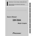
GM-X944
Connection Diagram
Fuse (30 A) � 2 Grommet Special red battery wire [RD-223] (sold separately). After making all other connections at the amplifier, connect the battery wire terminal of the amplifier to the positive (+) terminal of the battery.
Fuse (30 A) � 2
Ground wire (black) [RD-223] (sold separately). Connect to metal body or chassis.
RCA input Connecting wires with RCA pin plugs (sold separately).
Amplifier with RCA input jacks
Car stereo with RCA output jacks External Output For details on how to connect to RCA input jacks A and B, see the �Connecting the Speakers and Input wires� section.
Front side
RCA output jack
RCA input jack B RCA input jack A
Back side Fuse (30 A) � 3
Connecting wires with RCA pin plugs (sold separately).
Speaker output terminal
System remote control wire (sold separately) Connect the male terminal of this wire to the system remote control terminal of the car stereo (SYSTEM REMOTE CONTROL). The female terminal can be connected to the auto-antenna relay control terminal. If the car stereo does not have a system remote control terminal, connect the male terminal to the power terminal through the ignition switch.
28
|