|
There are currently no product reviews.
 ;
About the service it's very fast and reliable. About the manual the quality is high enough to read even the tiniest details on the wiring diagrams so you can't ask much more than that, let it alone for a manual of a product from 20 years ago. Thank you, very satisfied.
;
The downloaded quality was as good as the orignial
 ;
This is a great and complete Service Manual for the Sharp GF8585HB. Giving full and detailed technical insight. Good to find these manuals online.
;
Everything was ok with the manual. If I have a small complaint, is that I ordered it during the weekend and I think you guys were closed. But I did receive it late Sunday. I will surely order from you again
;
Best Service! Very fast and easy to handle. Fast Download an you can come back every day to download again
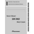
GM-X952
Connection Diagram
Fuse (30 A) Special red battery wire [RD-223] (sold separately) After making all other connections at the amplifier, connect the battery wire terminal of the amplifier to the positive (+) terminal of the battery. Fuse (30 A) Ground wire (black) [RD-223] (sold separately) Connect to metal body or chassis.
Grommet
Connecting wires with RCA pin plugs (sold separately).
Car stereo with RCA output jacks
External Output
Front side
RCA input jack
Back side Fuse (25 A) � 2 Speaker terminal System remote control wire (sold separately) Connect the male terminal of this wire to the system remote control terminal of the car stereo (SYSTEM REMOTE CONTROL). The female terminal can be connected to the auto-antenna relay control terminal. If the car stereo does not have a system remote control terminal, connect the male terminal to the power terminal through the ignition switch.
20
|