|
There are currently no product reviews.
 ;
PDF Contains
Technical Data, Mechanical data, Detailed Circuit diagram with components value, PCB layout. Actual PCBs Print. Component List, Spare parts code list and Input output detail. It cover LBB1211, LBB1212, LBB1213, LBB1216, LBB1217.
It is the actual Service Manual for SQ10
;
very good manual with clear electrical schemes. Very helpful to find wat was wrong inside my microwave.
 ;
Hi, thankyou for providing the Nordmende Globetrotter original manufacturer's repair manual. Quality is very good and sharp - the PDF file was comfortably small to download. The only question is: why did it take so long to become ready for download?? Many thanks anyway, I fixed the fault in the radio thanks to the circuit.
regards: Nick
;
This was super service.Ordered this manual and was reading the download an hour later
;
as always, rapid and efficient, very good and clear prints
details clearly visible keep going this way!!!!!!
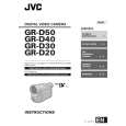
2.1.6 CHECKUP AND ADJUSTMENT OF MECHANISM PHASE
[24]MODE GEAR
Align the MODE GEAR with the Main Deck Assembly hole. Note: The MODE GEAR may be displaced during the mechanism operation, however it can be checked fr om the rear and realigned during manual assembly.
[27]ROTARY ENCODER
Mount the ROT ARY ENCODER by aligning its mark ( and the mark ( ) of the Main Deck Assembly. Note: Be careful when handling the FPC during mounting. )
[34]REEL GEAR 1
Align the REEL GEAR 1 with the Main Deck Assembly hole. Note: The REEL GEAR 1 may be displaced during mechanism operation, however this can be checked fr om the rear and realigned during manual assembly.
[29] MAIN CAM ASSY/[30]SLIDE ARM ASSY
When mounting the SLIDE ARM ASSY align it with the Main Deck Assembly and MAIN CAM ASSY holes. Note: During the mounting pr ocedure, make sure that the[32] SUB CAM ASSY is in the correct mounting position.
[32] SUB CAM ASSY/[33] CONTROL ARM ASSY
Mount the SUB CAM ASSY hole to align with the CONTROL ARM ASSY and Main Deck Assembly holes and then tighten them all together with a screw. Note: When mounting it, make sure that the[29]MAIN CAM ASSY is in the correct mounting position.
Fig.2-1-25
2-14 (No.86700)
 $4.99 GR-D20EK JVC
Owner's Manual Complete owner's manual in digital format. The manual will be available for download as PDF file aft…
|